Toyota Camry (XV70): GPS Antenna Connection Malfunction(short) (B15C0,B15C1)
DESCRIPTION
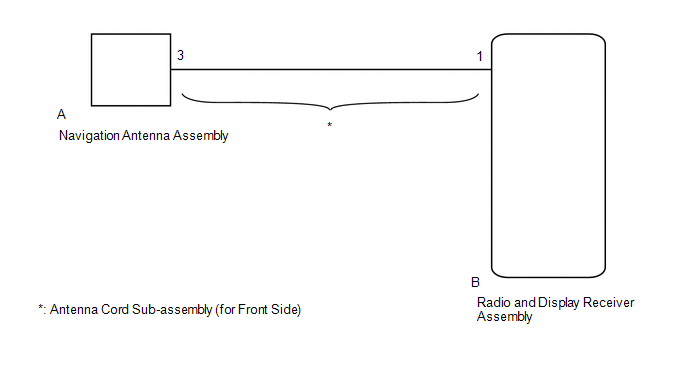
These DTCs are stored when a malfunction occurs in the navigation antenna assembly.
|
DTC No. | Detection Item |
DTC Detection Condition | Trouble Area |
|---|---|---|---|
|
B15C0 | GPS Antenna Connection Malfunction(short) |
Navigation antenna malfunction |
|
| B15C1 |
GPS Antenna Connection Malfunction(break) |
Navigation antenna power source malfunction |
|
WIRING DIAGRAM
CAUTION / NOTICE / HINT
NOTICE:
- Depending on the parts that are replaced during vehicle inspection or maintenance, performing initialization, registration or calibration may be needed. Refer to Precaution for Audio and Visual System.
Click here
.gif)
- When replacing the radio and display receiver assembly, always replace it with a new one. If a radio and display receiver assembly which was installed to another vehicle is used, the following may occur:
- A communication malfunction DTC may be stored.
- The radio and display receiver assembly may not operate normally.
- Check that the antenna cord sub-assembly (for Front Side) is properly installed and does not have any sharp bends, pinching or loose connections before performing following procedure.
Click here
PROCEDURE
|
1. | CHECK DTC |
(a) Clear the DTCs.
Body Electrical > Navigation System > Clear DTCs(b) Recheck for DTCs and check that no DTCs are output.
Body Electrical > Navigation System > Trouble CodesOK:
No DTCs are output.
| OK | .gif) |
USE SIMULATION METHOD TO CHECK |
|
.gif)
| 2. |
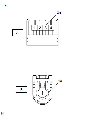
INSPECT ANTENNA CORD SUB-ASSEMBLY (for Front Side) |
(a) Remove the antenna cord sub-assembly (for Front Side).
Click here
| (b) Measure the resistance according to the value(s) in the table below. Standard Resistance:
|
|
| NG | | REPLACE ANTENNA CORD SUB-ASSEMBLY (for Front Side) |
|
| 3. |
INSPECT NAVIGATION ANTENNA ASSEMBLY |
(a) Remove the navigation antenna assembly.
Click here
(b) Inspect the navigation antenna assembly.
Click here
| OK | | REPLACE RADIO AND DISPLAY RECEIVER ASSEMBLY |
| NG | | REPLACE NAVIGATION ANTENNA ASSEMBLY |
READ NEXT:
 Speaker Output Short (B15C3)
DESCRIPTION This DTC is stored when a malfunction occurs in the speakers.
DTC No. Detection Item
DTC Detection Condition Trouble Area
B15C3 Speaker Output Short
A short
Stereo Component Amplifier Disconnected (B15D3)
DESCRIPTION The radio and display receiver assembly and stereo component amplifier assembly are connected by the AVC-LAN communication line.
DTC No. Detection Item
DTC Detection Condition
Telematics Transceiver Disconnected (B15DB)
DESCRIPTION If the radio and display receiver assembly cannot detect the DCM (telematics transceiver) for a certain period of time (90 seconds) after the ignition switch is turned to ACC and the radio
SEE MORE:
Components
COMPONENTS ILLUSTRATION
*1 NO. 2 RADIATOR HOSE
*2 WATER INLET WITH THERMOSTAT SUB-ASSEMBLY
*3 GASKET
*4 NO. 7 WATER BY-PASS HOSE
N*m (kgf*cm, ft.*lbf): Specified torque
● Non-reusable part
Installation
INSTALLATION CAUTION / NOTICE / HINT
HINT:
Use the same procedure for the RH side and LH side.
The following procedure is for the LH side.
PROCEDURE 1. TEMPORARILY INSTALL REAR AXLE CARRIER SUB-ASSEMBLY
(a) Temporarily install the rear axle carrier sub-assembly to the rear shock
