
Toyota Camry (XV70): Lost Communication with EMV Missing Message (B132187)
DESCRIPTION
The meter mirror sub-assembly receives signals from the radio and display receiver assembly via local bus communication and navigation system information on the headup display.
This DTC is stored when the meter mirror sub-assembly cannot receive the signal.
|
DTC No. | Detection Item |
DTC Detection Condition | Trouble Area |
Memory |
|---|---|---|---|---|
| B132187 |
Lost Communication with EMV Missing Message |
Diagnosis Condition:
Malfunction Status:
Malfunction Time:
|
| DTC stored |
WIRING DIAGRAM
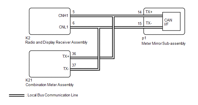
PROCEDURE
| 1. |
CHECK FOR DTC (NAVIGATION SYSTEM) |
(a) Check if navigation system DTCs are output.
Body Electrical > Navigation System > Trouble Codes|
Result | Proceed to |
|---|---|
|
DTCs are not output | A |
|
DTCs are output | B |
| B |
 | GO TO NAVIGATION SYSTEM |
|

| 2. |
CHECK FOR DTC (METER / GAUGE SYSTEM) |
(a) Check if meter / gauge system DTCs are output.
Click here 
|
Result | Proceed to |
|---|---|
|
DTC B132187 is not output |
A |
| DTC B132187 is output |
B |
| A |
| REPLACE METER MIRROR SUB-ASSEMBLY |
| B |
| REPLACE RADIO AND DISPLAY RECEIVER ASSEMBLY |
READ NEXT:
SEE MORE:
 Freeze Frame Data
FREEZE FRAME DATA FREEZE FRAME DATA (a) When a DTC is stored, the 4WD ECU assembly stores the current vehicle state as Freeze Frame Data.
HINT: Freeze Frame Data at the time a DTC is stored:
When the 4WD ECU assembly stores data at the time a DTC is stored, no updates will be performed until
AVC-LAN Circuit
DESCRIPTION Each unit of the audio and visual system connected to the AVC-LAN (communication bus) transmits signals via AVC-LAN communication.
If a short to +B or short to ground occurs in an AVC-LAN communication line, the audio and visual system will not function normally because communication i
