
Toyota Camry (XV70): Parts Location
PARTS LOCATION
ILLUSTRATION
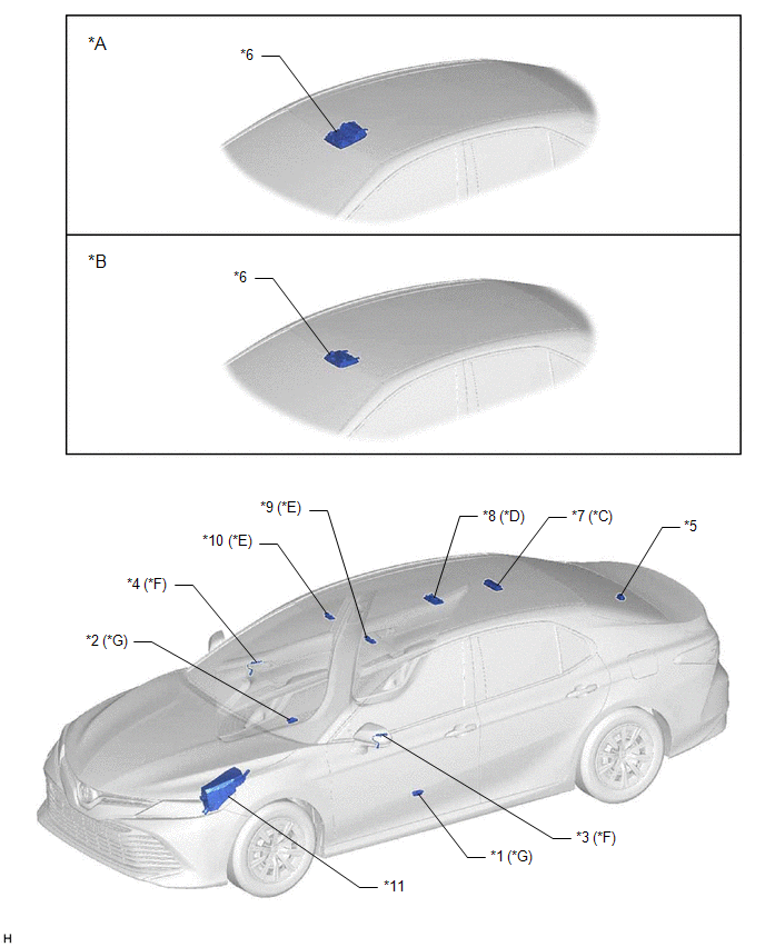
|
*A | for Normal Roof |
*B | except Normal Roof |
|
*C | w/ Room Light (for LED Type) |
*D | w/ Room Light (for Bulb Type) |
|
*E | w/ Vanity Light |
*F | w/ Inside Handle Illumination Light |
|
*G | w/ Courtesy Light |
- | - |
|
*1 | COURTESY LIGHT ASSEMBLY LH |
*2 | COURTESY LIGHT ASSEMBLY RH |
|
*3 | INSIDE HANDLE ILLUMINATION LIGHT LH (NO. 1 INTERIOR ILLUMINATION LIGHT ASSEMBLY LH) |
*4 | INSIDE HANDLE ILLUMINATION LIGHT RH (NO. 1 INTERIOR ILLUMINATION LIGHT ASSEMBLY RH) |
|
*5 | NO. 1 LUGGAGE COMPARTMENT LIGHT ASSEMBLY |
*6 | MAP LIGHT (ROOF CONSOLE BOX SUB-ASSEMBLY) |
|
*7 | SPOT LIGHT ASSEMBLY |
*8 | ROOM LIGHT ASSEMBLY |
|
*9 | VANITY LIGHT ASSEMBLY LH |
*10 | VANITY LIGHT ASSEMBLY RH |
|
*11 | ENGINE ROOM RELAY BLOCK AND JUNCTION BLOCK ASSEMBLY - ALT FUSE | - |
- |
ILLUSTRATION
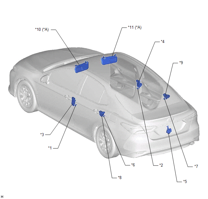
|
*A | w/ Vanity Light |
- | - |
|
*1 | FRONT DOOR COURTESY LIGHT SWITCH ASSEMBLY LH |
*2 | FRONT DOOR COURTESY LIGHT SWITCH ASSEMBLY RH |
|
*3 | FRONT DOOR LOCK WITH MOTOR ASSEMBLY LH |
*4 | FRONT DOOR LOCK WITH MOTOR ASSEMBLY RH |
|
*5 | LUGGAGE COMPARTMENT DOOR COURTESY LIGHT SWITCH (LUGGAGE COMPARTMENT DOOR LOCK ASSEMBLY) |
*6 | REAR DOOR COURTESY LIGHT SWITCH ASSEMBLY LH |
|
*7 | REAR DOOR COURTESY LIGHT SWITCH ASSEMBLY RH |
*8 | REAR DOOR LOCK WITH MOTOR ASSEMBLY LH |
|
*9 | REAR DOOR LOCK WITH MOTOR ASSEMBLY RH |
*10 | VISOR ASSEMBLY LH |
|
*11 | VISOR ASSEMBLY RH |
- | - |
ILLUSTRATION
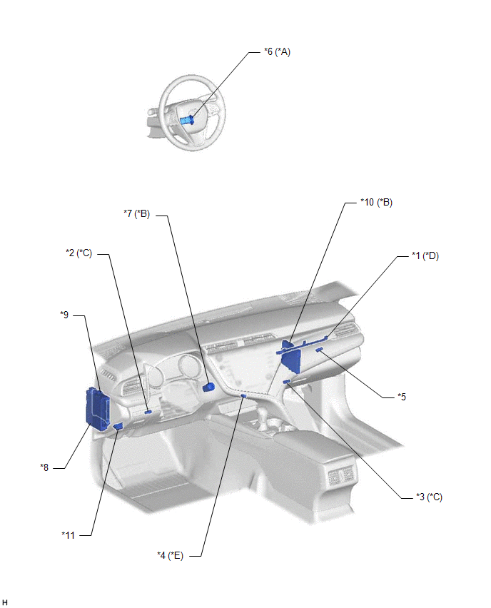
|
*A | w/o Smart Key System |
*B | w/ Smart Key System |
|
*C | w/ Footwell Light |
*D | w/ Instrument Panel Ambient Illumination Light |
|
*E | w/ Front Console Light |
- | - |
|
*1 | INSTRUMENT PANEL AMBIENT ILLUMINATION LIGHT (INSTRUMENT PANEL LIGHT ASSEMBLY) |
*2 | FOOTWELL LIGHT LH (NO. 1 INTERIOR ILLUMINATION LIGHT ASSEMBLY) |
|
*3 | FOOTWELL LIGHT RH (NO. 1 INTERIOR ILLUMINATION LIGHT ASSEMBLY) |
*4 | FRONT CONSOLE LIGHT (NO. 2 INTERIOR ILLUMINATION LIGHT SUB-ASSEMBLY) |
|
*5 | GLOVE BOX LIGHT ASSEMBLY |
*6 | IGNITION KEY CYLINDER LIGHT (TRANSPONDER KEY COIL) |
|
*7 | ENGINE SWITCH |
*8 | INSTRUMENT PANEL JUNCTION BLOCK ASSEMBLY - ECU-ACC FUSE - ECU-IG1 NO. 4 FUSE - DOME FUSE - ECU-DCC NO. 2 FUSE - ACC RELAY - IG1-NO. 1 RELAY - DOME CUT RELAY |
|
*9 | MAIN BODY ECU (MULTIPLEX NETWORK BODY ECU) |
*10 | CERTIFICATION ECU (SMART KEY ECU ASSEMBLY) |
|
*11 | DLC3 |
- | - |
READ NEXT:
SEE MORE:
 Removal
REMOVAL CAUTION / NOTICE / HINT
The necessary procedures (adjustment, calibration, initialization, or registration) that must be performed after parts are removed and installed, or replaced during front shock absorber assembly removal/installation are shown below. Necessary Procedures After Parts
Precaution
PRECAUTION IGNITION SWITCH EXPRESSIONS HINT:
The type of ignition switch used on this model differs depending on the specifications of the vehicle. The expressions listed in the table below are used in this section.
Expression Ignition Switch (Position)
Engine Switch (Condition)
