
Toyota Camry (XV70): Steering Pad Switch Circuit
DESCRIPTION
This circuit sends an operation signal from the steering pad switch assembly to the radio and display receiver assembly.
If there is an open in the circuit, the audio system cannot be operated using the steering pad switch assembly.
If there is a short in the circuit, the same condition as when a switch is continuously depressed occurs.
Therefore, the radio and display receiver assembly cannot be operated using the steering pad switch assembly, and the radio and display receiver assembly itself will not function.
WIRING DIAGRAM
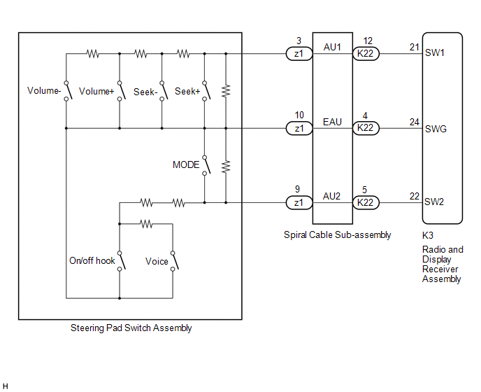
CAUTION / NOTICE / HINT
NOTICE:
The vehicle is equipped with a Supplemental Restraint System (SRS) which includes components such as airbags. Before servicing (including removal or installation of parts), be sure to read the precaution for Supplemental Restraint System.
Click here .gif)
PROCEDURE
| 1. |
CHECK HARNESS AND CONNECTOR (STEERING PAD SWITCH SIGNAL) |
(a) Disconnect the K3 radio and display receiver assembly connector.
(b) Measure the resistance according to the value(s) in the table below.
Standard Resistance:
|
Tester Connection | Condition |
Specified Condition |
|---|---|---|
|
K3-21 (SW1) - K3-24 (SWG) |
No switch pushed | 95 to 105 kΩ |
|
Seek+ switch pushed | Below 2.5 Ω | |
|
Seek- switch pushed | 313 to 345 Ω | |
|
Volume+ switch pushed |
950 to 1050 Ω | |
|
Volume- switch pushed |
2955 to 3265 Ω | |
|
K3-22 (SW2) - K3-24 (SWG) |
No switch pushed | 95 to 105 kΩ |
|
MODE switch pushed | Below 2.5 Ω | |
|
On/off hook switch pushed |
950 to 1050 Ω | |
|
Voice switch pushed | 2955 to 3265 Ω |
| OK | .gif) | PROCEED TO NEXT SUSPECTED AREA SHOWN IN PROBLEM SYMPTOMS TABLE
|
|
.gif)
| 2. |
INSPECT STEERING PAD SWITCH ASSEMBLY |
(a) Remove the steering pad switch assembly.
Click here
(b) Inspect the steering pad switch assembly.
Click here
| NG | | REPLACE STEERING PAD SWITCH ASSEMBLY
|
|
| 3. |
INSPECT SPIRAL CABLE SUB-ASSEMBLY |
(a) Remove the spiral cable sub-assembly.
Click here
(b) Inspect the spiral cable sub-assembly.
Click here
| OK | | REPAIR OR REPLACE HARNESS OR CONNECTOR (RADIO AND DISPLAY RECEIVER ASSEMBLY - SPIRAL CABLE SUB-ASSEMBLY) |
| NG | | REPLACE SPIRAL CABLE SUB-ASSEMBLY
|
READ NEXT:
 Illumination Circuit
DESCRIPTION Power is supplied to the radio and display receiver assembly and steering pad switch assembly illumination when the light control switch is in the tail or head position. WIRING DIAGRAM
Parking Brake Switch Circuit
DESCRIPTION This circuit is from the parking brake switch assembly*1 or skid control ECU (Brake Actuator Assembly)*2 to the radio and display receiver assembly.
*1: w/o Electric Parking Brake Sys
Speaker Circuit
DESCRIPTION for 6 Speakers
If there is a short in a speaker circuit, the radio and display receiver assembly detects it and stops output to the speakers.
Thus sound cannot be heard from the spe
SEE MORE:
Definition Of Terms
DEFINITION OF TERMS
Term Definition
Monitor description Description of what the ECM monitors and how it detects malfunctions (monitoring purpose and details).
Related DTCs Group of diagnostic trouble codes that are output by the ECM based on the same malfunction detection
Check For Intermittent Problems
CHECK FOR INTERMITTENT PROBLEMS CHECK FOR INTERMITTENT PROBLEMS
HINT: A momentary interruption (open circuit) in the connectors and/or wire harness between the sensors and ECUs can be detected using the Data List function of the Techstream.
(a) Turn the ignition switch off. (b) Connect the Techs
