
Toyota Camry (XV70): System Description
SYSTEM DESCRIPTION
HEADUP DISPLAY SYSTEM DESCRIPTION
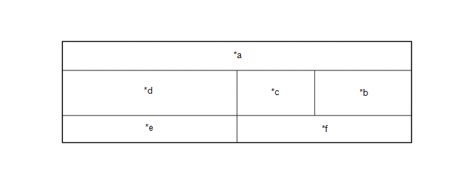
(a) The headup display system receives signals from each ECU via CAN communication and local bus communication and displays driving assist information, such as current vehicle speed, on the windshield glass assembly. The brightness and position of the headup display can be changed on the settings screen of the multi-information display. Depending on certain conditions, the following items can be displayed on the headup display:
|
*a | Display Area A |
*b | Display Area B |
|
*c | Display Area C |
*d | Display Area D |
|
*e | Display Area E |
*f | Display Area F |
|
Display Area | Display |
|---|---|
|
A, B, C, D, E, F | Pre-collision system warning message |
|
Parking support brake system warning message*1 | |
|
Opening | |
| A, C, D, E, F |
Parking support brake system caution message*1 |
|
A, D, E, F | Display position adjustment frame |
|
D, E | Dynamic radar cruise control system warning |
|
Lane tracing assist system warning | |
|
Clearance sonar detection*1 | |
|
Route guidance to destination (Navigation system) | |
|
B | Speedometer |
|
Speedometer unit | |
|
Traffic Sign*2 | |
|
C | Shift position |
|
Speed limit (Navigation system) | |
|
D | Dynamic radar cruise control system information |
|
Lane tracing assist system information | |
|
Compass (Navigation system) | |
|
Street name (Navigation system) | |
|
Curve speed reduction indicator | |
|
E | Unsteady driving alert |
|
Hands off steering wheel alert | |
|
Master warning light | |
|
Icy warning light | |
|
Information | |
|
Dynamic radar cruise control system notification message | |
|
Audio system operation status | |
|
Hands-free system status | |
|
F | Outside temperature |
|
Eco driving indicator zone | |
|
Tachometer |
- *1: w/ Parking Support Brake System
- *2: w/ Road Sign Assist System
READ NEXT:
SEE MORE:
 Before Starting Driving Adjustment
BEFORE STARTING DRIVING ADJUSTMENT CAUTION / NOTICE / HINT
NOTICE: When replacing the windshield glass of a vehicle equipped with a forward recognition camera, make sure to use a Toyota genuine part. If a non-Toyota genuine part is used, the forward recognition camera may not be able to be install
Parts Location
PARTS LOCATION ILLUSTRATION
*1 FUEL SENDER GAUGE ASSEMBLY
*2 FUEL PUMP (for Low Pressure)
*3 FUEL PUMP CONTROL ECU
*4 FUEL TANK ASSEMBLY
*5 FUEL SUCTION TUBE WITH PUMP AND GAUGE ASSEMBLY
*6 FUEL MAIN VALVE ASSEMBLY (for Low Pressure)
*7
