Toyota Camry (XV70): System Diagram
SYSTEM DIAGRAM
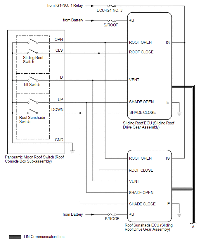
 Communication Table
 |
Sender | Receiver |
Signal | Line |
|---|---|---|---|
|
Main Body ECU (Multiplex Network Body ECU) |
Sliding Roof ECU (Sliding Roof Drive Gear Assembly) |
| LIN |
|
Main Body ECU (Multiplex Network Body ECU) |
Roof Sunshade ECU (Sliding Roof Drive Gear Assembly) |
| LIN |
|
Sliding Roof ECU (Sliding Roof Drive Gear Assembly) |
Main Body ECU (Multiplex Network Body ECU) |
Sliding roof glass position signal |
LIN |
| Sliding Roof ECU (Sliding Roof Drive Gear Assembly) |
Roof Sunshade ECU (Sliding Roof Drive Gear Assembly) |
| LIN |
|
Roof Sunshade ECU (Sliding Roof Drive Gear Assembly) |
Sliding Roof ECU (Sliding Roof Drive Gear Assembly) |
| LIN |
|
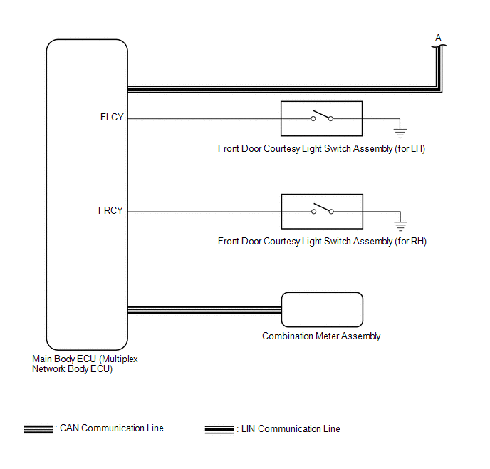
Combination Meter Assembly |
Main Body ECU (Multiplex Network Body ECU) |
Vehicle speed signal |
CAN |
| Main Body ECU (Multiplex Network Body ECU) |
Combination Meter Assembly | Sliding roof open warning request signal |
CAN |
READ NEXT:
 System Description
SYSTEM DESCRIPTION PANORAMIC MOON ROOF SYSTEM DESCRIPTION
(a) The panoramic moon roof system controls the sliding roof operation using the sliding roof ECU (sliding roof drive gear assembly) and ro
How To Proceed With Troubleshooting
CAUTION / NOTICE / HINT
HINT:
Use the following procedure to troubleshoot the panoramic moon roof system.
*: Use the Techstream.
PROCEDURE
1. VEHICLE BROUGHT TO WORKSHOP
Operation Check
OPERATION CHECK CHECK AUTO OPERATION FUNCTION (FOR SLIDING ROOF)
NOTICE:
Make sure that initialization has been completed before performing this inspection.
Click here
The sliding roo
SEE MORE:
Pressure Control Solenoid "H" Circuit Short to Ground or Open (P281614)
DESCRIPTION Refer to DTC P281612. Click here
DTC No. Detection Item
DTC Detection Condition Trouble Area
MIL Memory
Note P281614
Pressure Control Solenoid "H" Circuit Short to Ground or Open
While the vehicle is being driven so that gear changes occur,
Engine Circuit Malfunction (C1280)
DESCRIPTION If a malfunction in the ECM circuit occurs, the 4WD ECU assembly will output this DTC.
DTC No. Detection Item
DTC Detection Condition Trouble Area
C1280 Engine Circuit Malfunction
When the following continues for 5 seconds or more:
Communication wi
