
Toyota Camry (XV70): Terminals Of Ecu
TERMINALS OF ECU
CHECK INSTRUMENT PANEL JUNCTION BLOCK ASSEMBLY AND MAIN BODY ECU (MULTIPLEX NETWORK BODY ECU)
.png)
(a) Remove the main body ECU (multiplex network body ECU) from the instrument panel junction block assembly.
Click here .gif)
(b) Reconnect the instrument panel junction block assembly connectors.
(c) Measure the voltage and resistance according to the value(s) in the table below.
|
Terminal No. (Symbol) | Wiring Color |
Input/Output | Terminal Description |
Condition | Specified Condition |
Related Data List Item |
|---|---|---|---|---|---|---|
|
MB-11 (GND1) - Body ground |
- | - |
Ground | Always |
Below 1 ? | - |
|
MB-30 (ACC) - Body ground |
- | Input |
ACC power supply | Engine switch on (ACC) |
11 to 14 V |
ACC SW |
| Engine switch off |
Below 1 V | |||||
|
MB-31 (BECU) - Body ground |
- | Input |
Battery power supply |
Always | 11 to 14 V |
- |
|
MB-32 (IG) - Body ground |
- | Input |
IG power supply | Engine switch on (IG) |
11 to 14 V |
IG SW |
| Engine switch off |
Below 1 V |
(d) Install the main body ECU (multiplex network body ECU) to the instrument panel junction block assembly.
Click here
(e) Measure the voltage and check for pulses according to the value(s) in the table below.
|
Terminal No. (Symbol) | Wiring Color |
Input/Output | Terminal Description |
Condition | Specified Condition |
Related Data List Item |
|---|---|---|---|---|---|---|
|
3C-29 (BZR) - Body ground |
L - Body ground |
Output | Wireless door lock buzzer output |
Active Test Wireless Buzzer is OFF |
Below 1 V |
- |
| Active Test Wireless Buzzer is ON |
Pulse generation (frequency: 2 kHz, high voltage: 11 to 14 V, low voltage: below 1 V) |
CHECK CERTIFICATION ECU (SMART KEY ECU ASSEMBLY)
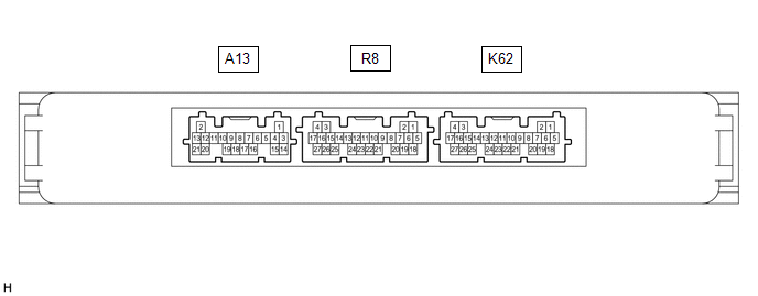
(a) Disconnect the K62 certification ECU (smart key ECU assembly) connector.
(b) Measure the voltage and resistance according to the value(s) in the table below.
|
Terminal No. (Symbol) | Wiring Color |
Input/Output | Terminal Description |
Condition | Specified Condition |
Related Data List Item |
|---|---|---|---|---|---|---|
|
K62-4 (+B) - Body ground |
W - Body ground | Input |
Battery power supply |
Always | 11 to 14 V |
- |
| K62-18 (E) - Body ground |
W-B - Body ground | - |
Ground | Always |
Below 1 ? | - |
(c) Reconnect the K62 certification ECU (smart key ECU assembly) connector.
(d) Check for pulses according to the value(s) in the table below.
|
Terminal No. (Symbol) | Wiring Color |
Input/Output | Terminal Description |
Condition | Specified Condition |
Related Data List Item |
|---|---|---|---|---|---|---|
|
R8-18 (RCO) - K62-18 (E) |
B - W-B | Output |
Output to electrical key and tire pressure monitoring system receiver assembly (Power supply for electrical key and tire pressure monitoring system receiver assembly. Certification ECU (smart key ECU assembly) outputs 5 V when receiver starts operating.) | Procedure:
| Plus generation (See waveform 1) |
- |
| R8-19 (RDAM) - K62-18 (E) |
G - W-B | Input |
Electrical key and tire pressure monitoring system receiver assembly communication circuit | Procedure:
| Plus generation (See waveform 2) |
- |
| R8-20 (CSEL) - K62-18 (E) |
BE - W-B | Output |
Communication channel switching circuit | Procedure:
| No pulse generation > Pulse generation |
- |
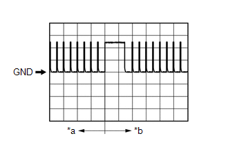
(e) Using an oscilloscope, check waveform 1.
HINT:
The oscilloscope waveform shown in the illustration is an example for reference only. Noise, chattering, etc. are not shown.
|
*a | Before lock or unlock switch of electrical key transmitter sub-assembly pressed |
|
*b | After lock or unlock switch of electrical key transmitter sub-assembly pressed |
|
Item | Content |
|---|---|
|
Tester connection | R8-18 (RCO) - K62-18 (E) |
|
Tool setting | 2 V/DIV., 500 ms/DIV. |
|
Condition | Procedure:
|
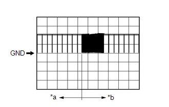
(f) Using an oscilloscope, check waveform 2.
HINT:
The oscilloscope waveform shown in the illustration is an example for reference only. Noise, chattering, etc. are not shown.
|
*a | Before lock or unlock switch of electrical key transmitter sub-assembly pressed |
|
*b | After lock or unlock switch of electrical key transmitter sub-assembly pressed |
|
Item | Content |
|---|---|
|
Tester connection | R8-19 (RDAM) - K62-18 (E) |
|
Tool setting | 5 V/DIV., 500 ms/DIV. |
|
Condition | Procedure:
|
READ NEXT:
 Dtc Check / Clear
DTC CHECK / CLEAR
NOTICE:
If DTCs are output, save and check all output DTCs.
When using the Techstream with the engine switch off, connect the Techstream to the DLC3 and turn a courtesy light sw
Data List / Active Test
DATA LIST / ACTIVE TEST DATA LIST NOTICE:
In the table below, the values listed under "Normal Condition" are reference values. Do not depend solely on these reference values when deciding whether a p
Diagnostic Trouble Code Chart
DIAGNOSTIC TROUBLE CODE CHART Wireless Door Lock Control System
DTC No. Detection Item
Link B1242
Wireless Door Lock Tuner Circuit Malfunction
SEE MORE:
VC Output Circuit
DESCRIPTION The ECM constantly generates a 5 V power source voltage from the battery voltage supplied to the +B, +B2 (BATT) terminals to operate the microprocessor. The ECM also provides this power to the sensors through the VC output circuit.
When the VC circuit has a short circuit, the micropro
FL Speed Sensor Wrong Installation (X0451)
DESCRIPTION
Code Tester Display
Measurement Item Trouble Area
X0451 FL Speed Sensor Wrong Installation
History of front speed sensor LH being installed incorrectly
Front speed sensor LH PROCEDURE
1.
CHECK FOR DTCs (HEALTH CHECK) (a) Perform the H
