Toyota Camry (XV70): Certification ECU Communication Stop Mode
DESCRIPTION
|
Detection Item | Symptom |
Trouble Area |
|---|---|---|
| Certification ECU Communication Stop Mode |
Any of the following conditions are met:
|
|
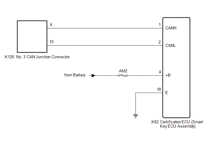
WIRING DIAGRAM
CAUTION / NOTICE / HINT
CAUTION:
When performing the confirmation driving pattern, obey all speed limits and traffic laws.
NOTICE:
- Because the order of diagnosis is important to allow correct diagnosis, make sure to begin troubleshooting using How to Proceed with Troubleshooting when CAN communication system related DTCs are output.
Click here
.gif)
- Before measuring the resistance of the CAN bus, turn the ignition switch off and leave the vehicle for 1 minute or more without operating the key or any switches, or opening or closing the doors. After that, disconnect the cable from the negative (-) battery terminal and leave the vehicle for 1 minute or more before measuring the resistance.
- After turning the ignition switch off, waiting time may be required before disconnecting the cable from the negative (-) battery terminal. Therefore, make sure to read the disconnecting the cable from the negative (-) battery terminal notices before proceeding with work.
Click here
- After performing repairs, perform the DTC check procedure and confirm that the DTCs are not output again.
DTC check procedure: Turn the ignition switch to ON and wait for 1 minute or more. Then operate the suspected malfunctioning system and drive the vehicle at 60 km/h (37 mph) or more for 5 minutes or more.
- After the repair, perform the CAN bus check and check that all the ECUs and sensors connected to the CAN communication system are displayed as normal.
Click here
- Inspect the fuses for circuits related to this system before performing the following procedure.
- Before replacing the certification ECU (smart key ECU assembly), refer to Registration.
Click here
HINT:
- Before disconnecting related connectors for inspection, push in on each connector body to check that the connector is not loose or disconnected.
- When a connector is disconnected, check that the terminals and connector body are not cracked, deformed or corroded.
PROCEDURE
|
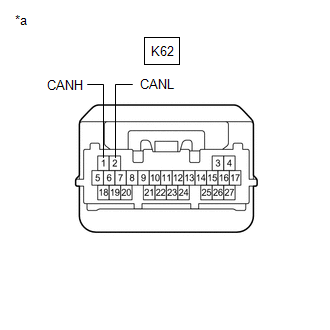
1. | CHECK FOR OPEN IN CAN BUS LINES (CERTIFICATION ECU (SMART KEY ECU ASSEMBLY) BRANCH LINE) |
(a) Disconnect the cable from the negative (-) battery terminal.
(b) Disconnect the K62 certification ECU (smart key ECU assembly) connector.
| (c) Measure the resistance according to the value(s) in the table below. Standard Resistance:
|
|
| NG | .gif) | REPAIR OR REPLACE CAN BRANCH LINES OR CONNECTOR (CERTIFICATION ECU (SMART KEY ECU ASSEMBLY)) |
|
.gif)
| 2. |
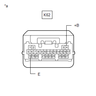
CHECK HARNESS AND CONNECTOR (POWER SOURCE CIRCUIT) |
| (a) Measure the resistance according to the value(s) in the table below. Standard Resistance:
|
|
(b) Reconnect the cable to the negative (-) battery terminal.
(c) Measure the voltage according to the value(s) in the table below.
Standard Voltage:
|
Tester Connection | Condition |
Specified Condition |
|---|---|---|
|
K62-4 (+B) - Body ground |
Always | 11 to 14 V |
| OK | | REPLACE CERTIFICATION ECU (SMART KEY ECU ASSEMBLY)
|
| NG | | REPAIR OR REPLACE HARNESS OR CONNECTOR (POWER SOURCE CIRCUIT) |
READ NEXT:
 Center Airbag Sensor Communication Stop Mode
DESCRIPTION
Detection Item Symptom
Trouble Area Center Airbag Sensor Communication Stop Mode
Any of the following conditions are met:
Communication stop for "Airbag" is
4WD Control ECU Communication Stop Mode
DESCRIPTION
Detection Item Symptom
Trouble Area 4WD Control ECU Communication Stop Mode
Any of the following conditions are met:
Communication stop for "Four Wheel Driv
Radio Receiver Assembly Communication Stop Mode
DESCRIPTION
Detection Item Symptom
Trouble Area Radio Receiver Assembly Communication Stop Mode
Any of the following conditions are met:
Communication stop for "Display
SEE MORE:
Registration
REGISTRATION CAUTION / NOTICE / HINT
NOTICE:
When the automatic transaxle assembly is replaced, the transaxle compensation code must be registered to the ECM (proceed to Procedure 1).
After the automatic transaxle assembly is installed, the Quick Response (QR) code label will be positioned w
Switch Failure (B2342)
DESCRIPTION This DTC is stored when the sliding roof ECU (sliding roof drive gear sub-assembly) detects that the sliding roof switch (roof console box sub-assembly) is stuck for 30 seconds or more.
DTC No. Detection Item
DTC Detection Condition
Trouble Area
B2342 Swit
