Toyota Camry (XV70): Components
COMPONENTS
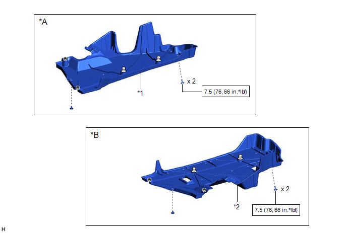
ILLUSTRATION
|
*A | for RH Side |
*B | for LH Side |
|
*1 | NO. 1 FLOOR UNDER COVER |
*2 | NO. 2 FLOOR UNDER COVER |
.png) |
N*m (kgf*cm, ft.*lbf): Specified torque |
- | - |
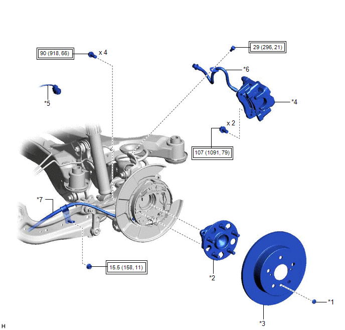
ILLUSTRATION
|
*1 | PARKING BRAKE SHOE ADJUSTING HOLE PLUG |
*2 | REAR AXLE HUB AND BEARING ASSEMBLY |
|
*3 | REAR DISC |
*4 | REAR DISC BRAKE CALIPER ASSEMBLY |
|
*5 | SKID CONTROL SENSOR WIRE |
*6 | REAR FLEXIBLE HOSE |
|
*7 | NO. 3 PARKING BRAKE CABLE ASSEMBLY |
- | - |
.png) |
Tightening torque for "Major areas involving basic vehicle performance such as moving/turning/stopping" : N*m (kgf*cm, ft.*lbf) |
- | - |
ILLUSTRATION

|
*1 | REAR FLEXIBLE HOSE BRACKET |
*2 | PARKING BRAKE ASSEMBLY |
|
*3 | REAR AXLE CARRIER SUB-ASSEMBLY |
*4 | REAR COIL SPRING |
|
*5 | REAR LOWER COIL SPRING INSULATOR |
*6 | REAR NO. 1 SUSPENSION ARM ASSEMBLY |
|
*7 | REAR NO. 2 SUSPENSION ARM ASSEMBLY |
*8 | REAR STABILIZER LINK ASSEMBLY |
|
*9 | REAR TRAILING ARM ASSEMBLY |
*10 | REAR STABILIZER BAR |
|
*11 | REAR UPPER CONTROL ARM ASSEMBLY |
*12 | REAR SHOCK ABSORBER ASSEMBLY |
|
*13 | REAR SUSPENSION TOE ADJUST CAM SUB-ASSEMBLY |
*14 | NO. 2 CAMBER ADJUST CAM |
|
*15 | PLATE WASHER |
- | - |
|
|
Tightening torque for "Major areas involving basic vehicle performance such as moving/turning/stopping" : N*m (kgf*cm, ft.*lbf) |
* | For use with a ball joint lock nut wrench |
READ NEXT:
 Removal
REMOVAL CAUTION / NOTICE / HINT
The necessary procedures (adjustment, calibration, initialization, or registration) that must be performed after parts are removed and installed, or replaced during r
Installation
INSTALLATION CAUTION / NOTICE / HINT
HINT:
Use the same procedure for the RH side and LH side.
The following procedure is for the LH side.
PROCEDURE 1. TEMPORARILY INSTALL REAR AXLE CARR
SEE MORE:
Relay
On-vehicle InspectionON-VEHICLE INSPECTION PROCEDURE
1. INSPECT DEF RELAY
(a) Measure the resistance according to the value(s) in the table below.
Standard Resistance:
Tester Connection
Condition Specified Condition
3 - 4 Battery voltage applied between te
Rear Door LH ECU Communication Stop (B2324)
DESCRIPTION This DTC is stored when LIN communication between the power window regulator motor assembly (for rear door LH) and main body ECU (multiplex network body ECU) stops for 10 seconds or more.
DTC No. Detection Item
DTC Detection Condition Trouble Area
B2324 Rear Door
