Toyota Camry (XV70): Components
COMPONENTS
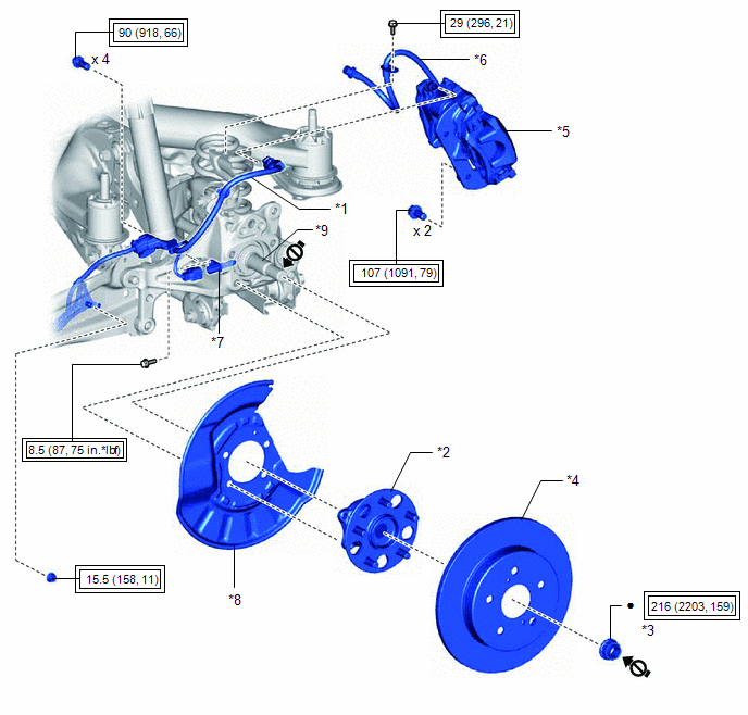
ILLUSTRATION
|
*1 | NO. 2 PARKING BRAKE WIRE ASSEMBLY |
*2 | REAR AXLE HUB AND BEARING ASSEMBLY |
|
*3 | REAR AXLE SHAFT NUT |
*4 | REAR DISC |
|
*5 | REAR DISC BRAKE CALIPER ASSEMBLY |
*6 | REAR FLEXIBLE HOSE |
|
*7 | REAR SKID CONTROL SENSOR |
*8 | REAR DISC BRAKE DUST COVER SUB-ASSEMBLY |
|
*9 | REAR DRIVE SHAFT ASSEMBLY |
- | - |
.png) |
Tightening torque for "Major areas involving basic vehicle performance such as moving/turning/stopping": N*m (kgf*cm, ft.*lbf) |
● | Non-reusable part |
.png) |
Do not apply lubricants to the threaded parts |
- | - |
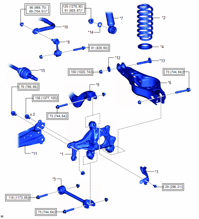
ILLUSTRATION
|
*1 | REAR AXLE CARRIER SUB-ASSEMBLY |
*2 | REAR COIL SPRING |
|
*3 | REAR FLEXIBLE HOSE BRACKET |
*4 | REAR LOWER COIL SPRING INSULATOR |
|
*5 | REAR NO. 1 SUSPENSION ARM ASSEMBLY |
*6 | REAR NO. 2 SUSPENSION ARM ASSEMBLY |
|
*7 | REAR SHOCK ABSORBER ASSEMBLY |
*8 | REAR STABILIZER LINK ASSEMBLY |
|
*9 | REAR UPPER CONTROL ARM ASSEMBLY |
*10 | REAR STABILIZER BAR |
|
*11 | REAR TRAILING ARM ASSEMBLY |
*12 | NO. 2 CAMBER ADJUST CAM |
|
*13 | REAR SUSPENSION TOE ADJUST CAM SUB-ASSEMBLY |
*14 | PLATE WASHER |
|
*15 | REAR DRIVE SHAFT ASSEMBLY |
- | - |
|
|
Tightening torque for "Major areas involving basic vehicle performance such as moving/turning/stopping": N*m (kgf*cm, ft.*lbf) |
* | For use with a ball joint lock nut wrench |
READ NEXT:
 Removal
REMOVAL CAUTION / NOTICE / HINT
The necessary procedures (adjustment, calibration, initialization, or registration) that must be performed after parts are removed and installed, or replaced during r
Installation
INSTALLATION CAUTION / NOTICE / HINT
HINT:
Use the same procedure for the RH side and LH side.
The following procedure is for the LH side.
PROCEDURE 1. TEMPORARILY INSTALL REAR AXLE CARR
SEE MORE:
Reassembly
REASSEMBLY PROCEDURE 1. BEARING POSITION
Check bearing position and installation direction.
Thrust Needle Roller Bearing and Bearing Race Diameter:
Mark Front Side Thrust Bearing Race Diameter Inside / Outside
mm (in.) Thrust Bearing Diameter Inside / Outside
mm (in.) Rear
Components
COMPONENTS ILLUSTRATION
*1 CAMSHAFT TIMING GEAR BOLT
*2 O-RING
*3 CAMSHAFT TIMING OIL CONTROL SOLENOID ASSEMBLY (for Intake Side of Bank 2)
- -
N*m (kgf*cm, ft.*lbf): Specified torque
● Non-reusable part
Adhesive 1324
