Toyota Camry (XV70): Installation
INSTALLATION
CAUTION / NOTICE / HINT
HINT:
- Use the same procedure for the RH side and LH side.
- The following procedure is for the LH side.
PROCEDURE
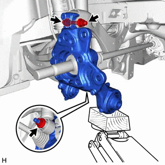
1. TEMPORARILY INSTALL REAR AXLE CARRIER SUB-ASSEMBLY
| (a) Temporarily install the rear axle carrier sub-assembly to the rear shock absorber assembly with the nut and plate washer. NOTICE: Hold the rear axle carrier pin while rotating the nut. |
|
(b) Temporarily install the rear axle carrier sub-assembly to the rear upper control arm assembly with the bolt and nut.
NOTICE:
- Insert the bolt with the threaded end facing the rear of the vehicle.
- Because the nut has its own stopper, do not turn the nut. Tighten the bolt with the nut secured.
| (c) Install the rear trailing arm assembly to the rear axle carrier sub-assembly with the 3 bolts and nut. Torque: Bolt A : 135 N |
READ NEXT:
 Components
COMPONENTS ILLUSTRATION
*1 NO. 2 PARKING BRAKE WIRE ASSEMBLY
*2 REAR AXLE HUB AND BEARING ASSEMBLY
*3 REAR DISC
*4 REAR DISC BRAKE CALIPER ASSEMBLY
*5 R
On-vehicle Inspection
ON-VEHICLE INSPECTION CAUTION / NOTICE / HINT
HINT:
Use the same procedure for the RH side and LH side.
The following procedure is for the LH side.
PROCEDURE 1. REMOVE REAR WHEEL Click h
SEE MORE:
ABS Warning Light Remains ON
DESCRIPTION This procedure is for troubleshooting when the ABS warning light remains on but no DTCs are output.
The skid control ECU (brake actuator assembly) controls the ABS warning light in the combination meter assembly via CAN communication. CAUTION / NOTICE / HINT
NOTICE:
After replaci
Replacement
REPLACEMENT CAUTION / NOTICE / HINT
The necessary procedures (adjustment, calibration, initialization or registration) that must be performed after parts are removed and installed, or replaced during automatic transaxle fluid replacement are shown below. Necessary Procedures After Parts Removed/In
© 2023-2026 Copyright www.tocamry.com
