Toyota Camry (XV70): On-vehicle Inspection
ON-VEHICLE INSPECTION
CAUTION / NOTICE / HINT
HINT:
- Use the same procedure for the RH side and LH side.
- The following procedure is for the LH side.
PROCEDURE
1. REMOVE REAR WHEEL
Click here
.gif)
2. DISCONNECT NO. 2 PARKING BRAKE WIRE ASSEMBLY
Click here
3. SEPARATE REAR DISC BRAKE CALIPER ASSEMBLY
Click here
4. REMOVE REAR DISC
Click here
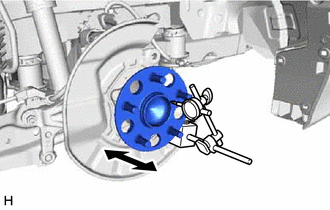
5. INSPECT REAR AXLE HUB BEARING LOOSENESS
| (a) Using a dial indicator with magnetic base, check for looseness near the center of the rear axle hub. Maximum Looseness: 0.05 mm (0.00196 in.) NOTICE:
HINT: If the looseness exceeds the maximum, replace the rear axle hub and bearing assembly. |
|
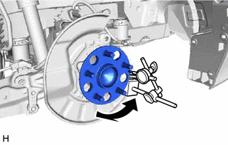
6. INSPECT REAR AXLE HUB RUNOUT
| (a) Using a dial indicator with magnetic base, check for runout on the surface of the rear axle hub outside the rear axle hub bolts. Maximum Runout: 0.05 mm (0.00196 in.) NOTICE:
HINT: If the runout exceeds the maximum, replace the rear axle hub and bearing assembly. |
|
7. INSTALL REAR DISC
Click here
8. INSTALL REAR DISC BRAKE CALIPER ASSEMBLY
Click here
9. CONNECT NO. 2 PARKING BRAKE WIRE ASSEMBLY
Click here
10. INSTALL REAR WHEEL
Click here
READ NEXT:
 Removal
REMOVAL CAUTION / NOTICE / HINT
HINT:
Use the same procedure for the RH side and LH side.
The following procedure is for the LH side.
PROCEDURE 1. REMOVE REAR WHEEL Click here
2. DIS
Installation
INSTALLATION CAUTION / NOTICE / HINT
HINT:
Use the same procedure for the RH side and LH side.
The following procedure is for the LH side.
PROCEDURE 1. INSTALL REAR AXLE HUB AND BEARING
SEE MORE:
Terminals Of Ecm
TERMINALS OF ECM ECM
HINT: The standard voltage and resistance of each ECM terminal is shown in the table below.
In the table, first follow the information under "Condition". Look under "Terminal No. (Symbol)" for the terminals to be inspected. The standard voltage or resistance between the ter
Parts Location
PARTS LOCATION ILLUSTRATION
*1 OUTER MIRROR SWITCH ASSEMBLY
*2 OUTER REAR VIEW MIRROR ASSEMBLY LH
*3 OUTER REAR VIEW MIRROR ASSEMBLY RH
*4 OUTER MIRROR LH
*5 OUTER MIRROR RH
*6 MIRROR SELECT AND SURFACE ADJUST SWITCH
*7 ENGIN
