Toyota Camry (XV70): Removal
REMOVAL
CAUTION / NOTICE / HINT
HINT:
- Use the same procedure for the RH side and LH side.
- The following procedure is for the LH side.
PROCEDURE
1. REMOVE REAR WHEEL
Click here
.gif)
2. DISCONNECT NO. 2 PARKING BRAKE WIRE ASSEMBLY
| (a) Disconnect the No. 2 parking brake wire assembly connector from the parking brake actuator assembly. NOTICE:
|
|
.png)
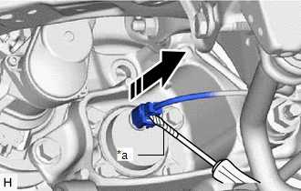
| (b) Using a screwdriver with its tip wrapped with protective tape, disconnect the No. 2 parking brake wire assembly connector from the rear axle hub and bearing assembly. NOTICE: Be careful not to damage the rear axle hub and bearing assembly or connector cover. |
|
3. SEPARATE REAR DISC BRAKE CALIPER ASSEMBLY
Click here
4. REMOVE REAR DISC
Click here
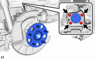
5. REMOVE REAR AXLE HUB AND BEARING ASSEMBLY
| (a) Remove the 4 bolts, rear axle hub and bearing assembly and rear disc brake dust cover sub-assembly from the rear axle carrier sub-assembly. |
|
READ NEXT:
 Installation
INSTALLATION CAUTION / NOTICE / HINT
HINT:
Use the same procedure for the RH side and LH side.
The following procedure is for the LH side.
PROCEDURE 1. INSTALL REAR AXLE HUB AND BEARING
Components
COMPONENTS ILLUSTRATION
*1 PARKING BRAKE SHOE ADJUSTING HOLE PLUG
*2 REAR AXLE HUB AND BEARING ASSEMBLY
*3 REAR DISC
*4 REAR DISC BRAKE CALIPER ASSEMBLY
*
SEE MORE:
O2 Sensor Slow Response - Rich to Lean Bank 1 Sensor 1 (P014C00-P014F00,P015A00-P015D00)
DESCRIPTION Refer to DTC P219519. Click here
HINT: Although the DTC titles say oxygen sensor, these DTCs relate to the air fuel ratio sensor.
DTC No. Detection Item
DTC Detection Condition Trouble Area
MIL Memory
Note P014C00
O2 Sensor Slow Response - Rich to
Installation
INSTALLATION CAUTION / NOTICE / HINT
HINT:
Use the same procedure for the RH side and LH side.
The following procedure is for the LH side.
PROCEDURE 1. TEMPORARILY INSTALL REAR AXLE CARRIER SUB-ASSEMBLY
(a) Temporarily install the rear axle carrier sub-assembly to the rear shock abso
