
Toyota Camry (XV70): Fuel Filter
Components
COMPONENTS
ILLUSTRATION
|
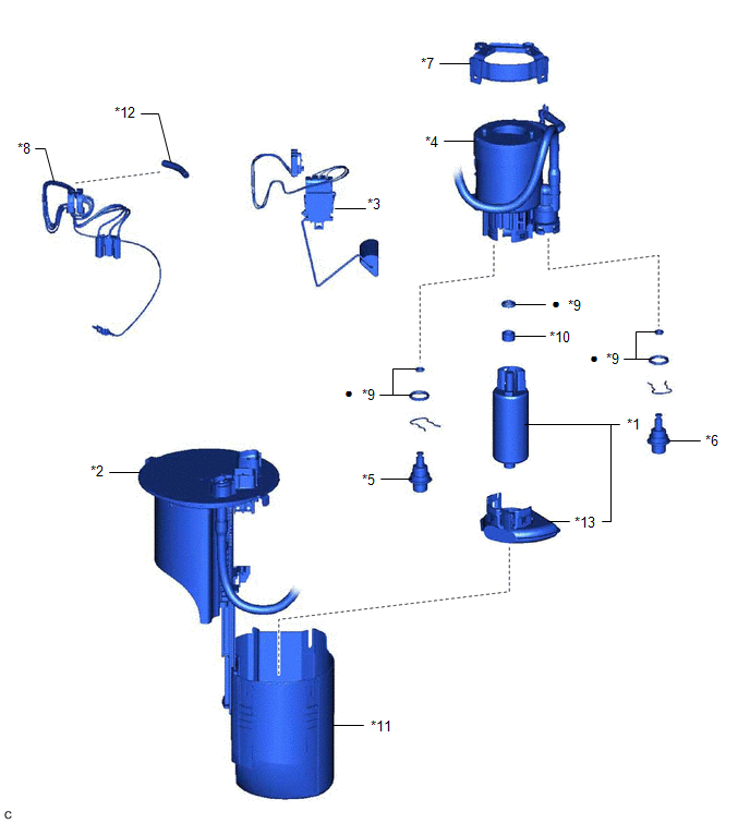
*1 | FUEL PUMP |
*2 | FUEL SUCTION PLATE SUB-ASSEMBLY |
|
*3 | FUEL SENDER GAUGE ASSEMBLY |
*4 | FUEL FILTER |
|
*5 | FUEL MAIN VALVE ASSEMBLY (for Low Pressure) |
*6 | FUEL MAIN VALVE ASSEMBLY (for High Pressure) |
|
*7 | NO. 1 FUEL SUCTION SUPPORT |
*8 | FUEL PUMP HARNESS |
|
*9 | O-RING |
*10 | FUEL PUMP SPACER |
|
*11 | FUEL SUB-TANK |
*12 | HARNESS PROTECTOR |
|
*13 | SUCTION FILTER |
- | - |
|
● | Non-reusable part |
- | - |
Replacement
REPLACEMENT
CAUTION / NOTICE / HINT
The necessary procedures (adjustment, calibration, initialization or registration) that must be performed after parts are removed and installed, or replaced during fuel filter removal/installation are shown below.
Necessary Procedures After Parts Removed/Installed/Replaced|
Replaced Part or Performed Procedure |
Necessary Procedure | Effect/Inoperative Function when Necessary Procedure not Performed |
Link |
|---|---|---|---|
|
Battery terminal is disconnected/reconnected |
Perform steering sensor zero point calibration |
Lane Tracing Assist System |
|
|
Pre-collision System | |||
|
Memorize steering angle neutral point |
Parking Assist Monitor System |
| |
|
Panoramic View Monitor System |
| ||
|
Replacement of fuel pump |
Inspection after repair |
|
|
CAUTION:
- Never perform work on fuel system components near any possible ignition sources.
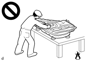
- Vaporized fuel could ignite, resulting in a serious accident.
- Do not perform work on fuel system components without first disconnecting the cable from the negative (-) battery terminal.
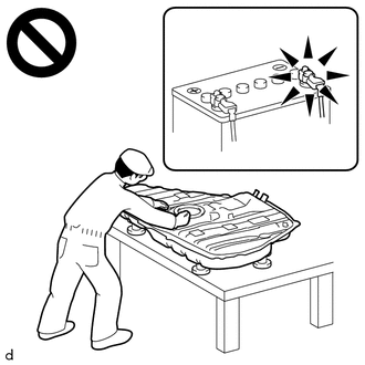
- Sparks could cause vaporized fuel to ignite, resulting in a serious accident.
PROCEDURE
1. REMOVE FUEL SUCTION TUBE WITH PUMP AND GAUGE ASSEMBLY
Click here .gif)
2. REMOVE FUEL SENDER GAUGE ASSEMBLY
Click here
3. REMOVE FUEL PUMP
Click here
4. REMOVE FUEL MAIN VALVE ASSEMBLY
Click here
5. REMOVE NO. 1 FUEL SUCTION SUPPORT
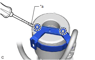
| (a) Using a screwdriver with its tip wrapped with protective tape, disengage the 2 claws and remove the No. 1 fuel suction support from the fuel filter. |
|
6. INSTALL NO. 1 FUEL SUCTION SUPPORT
(a) Engage the 2 claws to install the No. 1 fuel suction support to the fuel filter.
7. INSTALL FUEL MAIN VALVE ASSEMBLY
Click here
8. INSTALL FUEL PUMP
Click here
9. INSTALL FUEL SENDER GAUGE ASSEMBLY
Click here
10. INSTALL FUEL SUCTION TUBE WITH PUMP AND GAUGE ASSEMBLY
Click here
READ NEXT:
 Components
COMPONENTS ILLUSTRATION
*1 FUEL DELIVERY PIPE RH
*2 FUEL DELIVERY PIPE WITH SENSOR ASSEMBLY LH
*3 FUEL INJECTOR ASSEMBLY
*4 FUEL INJECTOR SEAL
*5 NO. 2
Removal
REMOVAL CAUTION / NOTICE / HINT
The necessary procedures (adjustment, calibration, initialization or registration) that must be performed after parts are removed and installed, or replaced during fu
SEE MORE:
Installation
INSTALLATION PROCEDURE 1. INSTALL HOLE PLUG
(a) Install the 7 hole plugs to the front frame assembly. HINT:
There are 2 different shapes of hole plug.
2. INSTALL FRONT SUSPENSION MEMBER BODY MOUNTING REAR CUSHION LH
(a) Align a new front suspension member body mounting rear cushion LH as sh
Reassembly
REASSEMBLY PROCEDURE 1. INSTALL SOLENOID (SL) VALVE
(a) Coat the solenoid (SL) valve with Toyota Genuine ATF WS.
(b) Install the solenoid (SL) valve to the transmission valve body assembly with the bolt.
Torque: 7.0 N
