Toyota Camry (XV70): Components
COMPONENTS
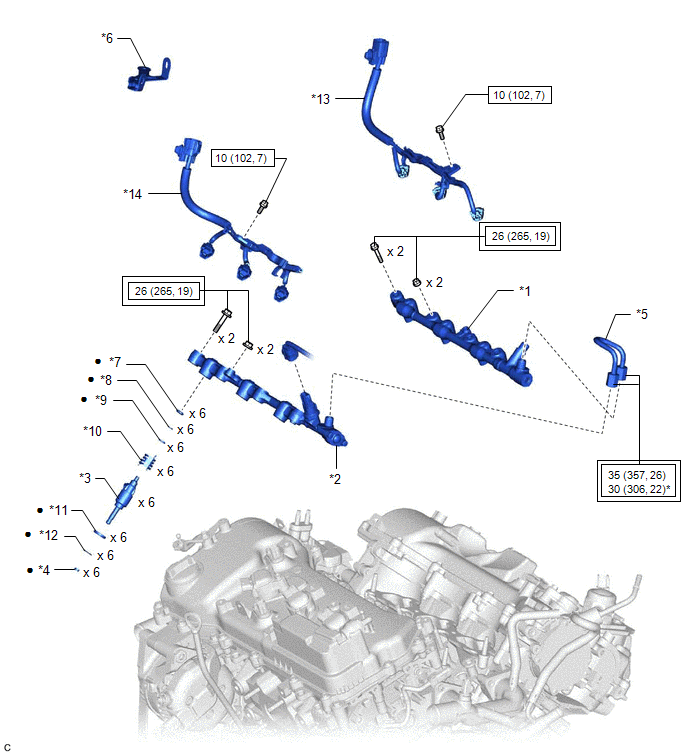
ILLUSTRATION
|
*1 | FUEL DELIVERY PIPE RH |
*2 | FUEL DELIVERY PIPE WITH SENSOR ASSEMBLY LH |
|
*3 | FUEL INJECTOR ASSEMBLY |
*4 | FUEL INJECTOR SEAL |
|
*5 | NO. 2 FUEL PIPE SUB-ASSEMBLY |
*6 | WIRE HARNESS CLAMP BRACKET |
|
*7 | NO. 3 FUEL INJECTOR BACK-UP RING |
*8 | O-RING |
|
*9 | NO. 1 FUEL INJECTOR BACK-UP RING |
*10 | NOZZLE HOLDER CLAMP |
|
*11 | INJECTOR VIBRATION INSULATOR |
*12 | C-RING |
|
*13 | NO. 6 ENGINE WIRE |
*14 | NO. 7 ENGINE WIRE |
.png) |
Tightening torque for "Major areas involving basic vehicle performance such as moving/turning/stopping": N*m (kgf*cm, ft.*lbf) |
.png) |
N*m (kgf*cm, ft.*lbf): Specified torque |
|
* | For use with a union nut wrench |
● | Non-reusable part |
READ NEXT:
 Removal
REMOVAL CAUTION / NOTICE / HINT
The necessary procedures (adjustment, calibration, initialization or registration) that must be performed after parts are removed and installed, or replaced during fu
Inspection
INSPECTION PROCEDURE 1. INSPECT FUEL INJECTOR ASSEMBLY
NOTICE: This inspection is for checking the fuel injector assembly for an open or short. Because the fuel injector assembly of this vehicle is
Installation
INSTALLATION PROCEDURE 1. INSTALL FUEL INJECTOR SEAL
(a) Apply engine conditioner to the area shown in the illustration. Using a piece of cloth, clean carbon deposits from the fuel injector asse
SEE MORE:
Disassembly
DISASSEMBLY PROCEDURE 1. REMOVE OIL FILLER CAP SUB-ASSEMBLY
(a) Remove the oil filler cap sub-assembly from the cylinder head cover sub-assembly LH.
(b) Remove the oil filler cap gasket from the oil filler cap sub-assembly.
2. REMOVE SPARK PLUG Cli
Installation
INSTALLATION PROCEDURE 1. INSTALL MILLIMETER WAVE RADAR SENSOR ASSEMBLY
NOTICE: If the millimeter wave radar sensor assembly has been struck or dropped, replace the millimeter wave radar sensor assembly with a new one.
(a) Engage the 2 guides.
Bolt
Screw (b) In
© 2023-2026 Copyright www.tocamry.com
