Toyota Camry (XV70): Installation
INSTALLATION
PROCEDURE
1. INSTALL HOLE PLUG
(a) Install the 7 hole plugs to the front frame assembly.
HINT:
There are 2 different shapes of hole plug.
.png)
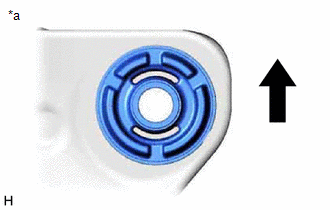
2. INSTALL FRONT SUSPENSION MEMBER BODY MOUNTING REAR CUSHION LH
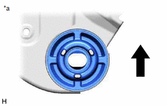
(a) Align a new front suspension member body mounting rear cushion LH as shown in the illustration and set it to the front frame assembly.
|
*a | View from Underneath |
.png) |
Front of the Vehicle |
NOTICE:
- Position the front suspension member body mounting rear cushion LH in the correct direction.
- Do not apply lubricant to the outer sleeve of the front suspension member body mounting rear cushion LH.
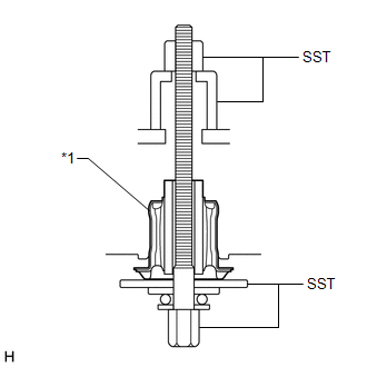
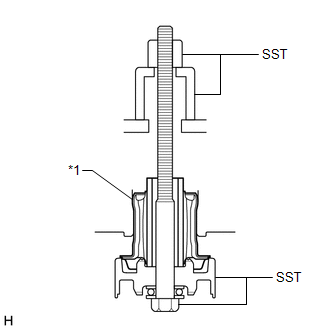
| (b) Install SST as shown in the illustration. SST: 09570-24011 SST: 09830-10010 09830-01010 09830-01020 09830-01040 09830-01060 NOTICE: Apply molybdenum grease to the threads and tip of the SST center bolt before use. |
|
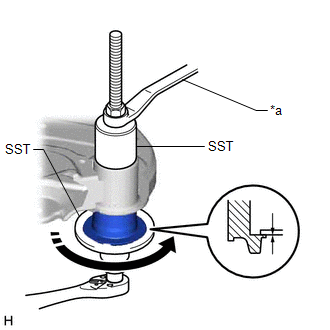
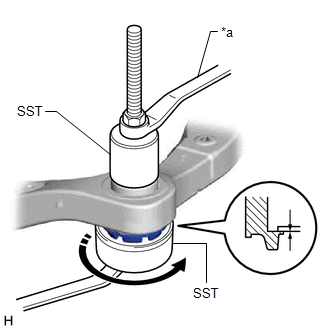
(c) Using SST, install the front suspension member body mounting rear cushion LH as shown in the illustration.
|
*a | Hold |
.png) |
Turn |
NOTICE:
Check that there is no clearance between the front frame assembly and the front suspension member body mounting rear cushion LH.
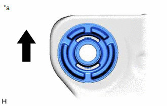
3. INSTALL FRONT SUSPENSION MEMBER BODY MOUNTING REAR CUSHION
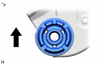
(a) Align a new front suspension member body mounting rear cushion as shown in the illustration and set it to the front frame assembly.
|
*a | View from Underneath |
|
|
Front of the Vehicle |
NOTICE:
- Position the front suspension member body mounting rear cushion in the correct direction.
- Do not apply lubricant to the outer sleeve of the front suspension member body mounting rear cushion.
(b) Install SST using the same procedure as for the front suspension member body mounting rear cushion LH.
SST: 09570-24011
SST: 09830-10010
09830-01010
09830-01020
09830-01040
09830-01060
NOTICE:
Apply molybdenum grease to the threads and tip of the SST center bolt before use.
(c) Using SST, install the front suspension member body mounting rear cushion.
NOTICE:
Check that there is no clearance between the front frame assembly and the front suspension member body mounting rear cushion.
HINT:
Perform the same procedure as for the front suspension member body mounting rear cushion LH.
4. INSTALL FRONT SUSPENSION MEMBER BODY MOUNTING FRONT CUSHION (for LH Side)
(a) Align a new front suspension member body mounting front cushion as shown in the illustration and set it to the front frame assembly.
|
*a | View from Underneath |
|
|
Front of the Vehicle |
NOTICE:
- Position the front suspension member body mounting front cushion in the correct direction.
- Do not apply lubricant to the outer sleeve of the front suspension member body mounting front cushion.
| (b) Install SST as shown in the illustration. SST: 09830-10010 09830-01010 09830-01020 09830-01030 09830-01060 NOTICE:
|
|
(c) Using SST, install the front suspension member body mounting front cushion as shown in the illustration.
|
*a | Hold |
|
|
Turn |
NOTICE:
Check that there is no clearance between the front frame assembly and the front suspension member body mounting front cushion.
5. INSTALL FRONT SUSPENSION MEMBER BODY MOUNTING FRONT CUSHION (for RH Side)
(a) Align a new front suspension member body mounting front cushion as shown in the illustration and set it to the front frame assembly.
|
*a | View from Underneath |
|
|
Front of the Vehicle |
NOTICE:
- Position the front suspension member body mounting front cushion in the correct direction.
- Do not apply lubricant to the outer sleeve of the front suspension member body mounting front cushion.
(b) Install SST using the same procedure as for the LH side.
SST: 09830-10010
09830-01010
09830-01020
09830-01030
09830-01060
NOTICE:
- Be sure to install SST (09830-01030) in the correct direction.
- Apply molybdenum grease to the threads and tip of the SST center bolt before use.
(c) Using SST, install the front suspension member body mounting front cushion.
NOTICE:
Check that there is no clearance between the front frame assembly and the front suspension member body mounting front cushion.
HINT:
Perform the same procedure as for the LH side.
6. INSTALL FRONT SUSPENSION MEMBER BODY MOUNTING REAR STOPPER
(a) Install the 2 front suspension member body mounting rear stoppers to the front frame assembly.
7. INSTALL FRONT SUSPENSION MEMBER BODY MOUNTING FRONT STOPPER
(a) Install the 2 front suspension member body mounting front stoppers to the front frame assembly.
8. INSTALL FRONT SUSPENSION MEMBER DYNAMIC DAMPER
(a) Install the front suspension member dynamic damper to the front frame assembly with the 2 bolts.
Torque:
29 N
READ NEXT:
 Problem Symptoms Table
PROBLEM SYMPTOMS TABLE HINT: Use the table below to help determine the cause of problem symptoms. If multiple suspected areas are listed, the potential causes of the symptoms are listed in order of pr
SEE MORE:
Antenna Cord
ComponentsCOMPONENTS ILLUSTRATION
*1 ANTENNA CORD SUB-ASSEMBLY
*2 INSTRUMENT PANEL SAFETY PAD SUB-ASSEMBLY
*3 NO. 2 SIDE DEFROSTER NOZZLE DUCT
*4 NO. 3 HEATER TO REGISTER DUCT SUB-ASSEMBLY RemovalREMOVAL CAUTION / NOTICE / HINT
The necessary procedures (adj
ABS Solenoid Control Module Actuator Stuck On (C143A7E,C143A7F,C143D49,C14DA14)
DESCRIPTION The ABS solenoid relay is built into the skid control ECU in the brake actuator assembly. The ABS solenoid relay supplies power to each solenoid.
The skid control ECU (brake actuator assembly) detects an ABS solenoid relay malfunction by performing a self check and relay operation chec
