Toyota Camry (XV70): Components
COMPONENTS
ILLUSTRATION
|
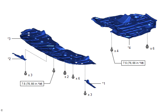
*1 | FRONT WHEEL OPENING EXTENSION PAD LH |
*2 | FRONT WHEEL OPENING EXTENSION PAD RH |
|
*3 | NO. 1 ENGINE UNDER COVER |
*4 | NO. 2 ENGINE UNDER COVER ASSEMBLY |
.png) |
N*m (kgf*cm, ft.*lbf): Specified torque |
- | - |
ILLUSTRATION
.png)
|
*1 | FRONT BUMPER ENERGY ABSORBER |
*2 | FRONT BUMPER REINFORCEMENT |
|
*3 | NO. 2 FRONT BUMPER ENERGY ABSORBER |
- | - |
|
|
N*m (kgf*cm, ft.*lbf): Specified torque |
- | - |
ILLUSTRATION
.png)
|
*A | for Bar Type Radiator Grille |
*B | for Mesh Type Radiator Grille |
|
*1 | NO. 1 RADIATOR AIR GUIDE LH |
*2 | NO. 1 RADIATOR AIR GUIDE RH |
ILLUSTRATION
|
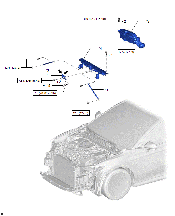
*1 | HOOD LOCK ASSEMBLY |
*2 | INLET AIR CLEANER ASSEMBLY |
|
*3 | UPPER RADIATOR MOUNTING BRACKET |
*4 | UPPER RADIATOR SUPPORT SUB-ASSEMBLY |
|
*5 | HOOD LOCK NUT CAP |
- | - |
|
|
N*m (kgf*cm, ft.*lbf): Specified torque |
● | Non-reusable part |
.png) |
MP grease | - |
- |
ILLUSTRATION
|
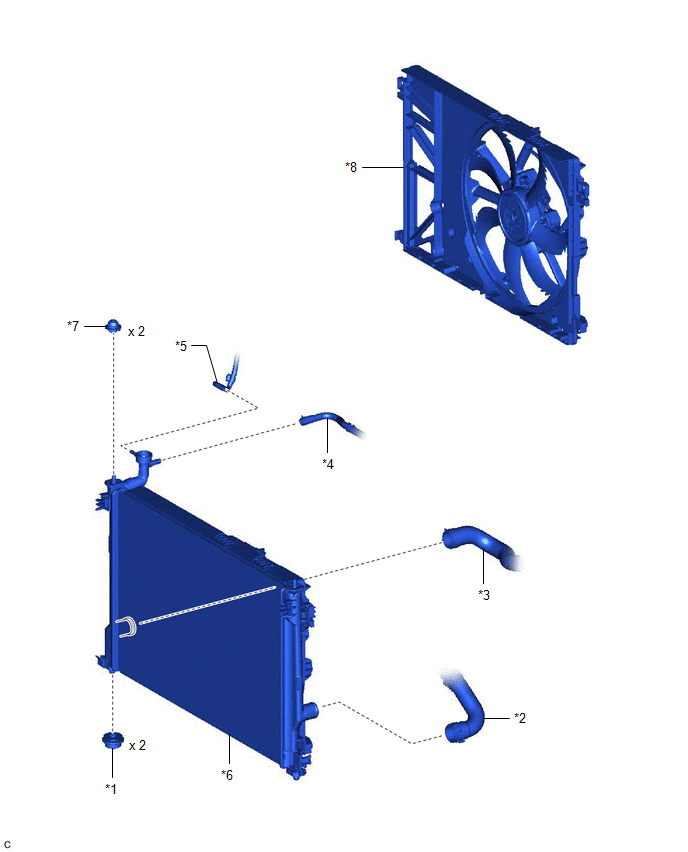
*1 | LOWER RADIATOR SUPPORT |
*2 | NO. 1 RADIATOR HOSE |
|
*3 | NO. 2 RADIATOR HOSE |
*4 | NO. 5 WATER BY-PASS HOSE |
|
*5 | NO. 6 WATER BY-PASS HOSE |
*6 | RADIATOR ASSEMBLY |
|
*7 | RADIATOR SUPPORT CUSHION |
*8 | FAN SHROUD ASSEMBLY |
READ NEXT:
 On-vehicle Inspection
ON-VEHICLE INSPECTION CAUTION / NOTICE / HINT
CAUTION: Do not remove the radiator cap sub-assembly while the engine and radiator assembly are still hot. Pressurized, hot engine coolant and steam may
Removal
REMOVAL CAUTION / NOTICE / HINT
The necessary procedures (adjustment, calibration, initialization or registration) that must be performed after parts are removed and installed, or replaced during ra
Installation
INSTALLATION PROCEDURE 1. INSTALL LOWER RADIATOR SUPPORT
(a) Install the 2 lower radiator supports to the radiator assembly. 2. INSTALL RADIATOR SUPPORT CUSHION
(a) Install the 2 radiator support
SEE MORE:
Brake Switch "A" Circuit Short to Ground (P057111)
DESCRIPTION The skid control ECU (brake actuator assembly) receives stop light switch assembly signals and uses them to determine whether or not the brakes are applied.
When the brake pedal is depressed and no signal is received from the stop light switch assembly, this DTC is output.
DTC No
Components
COMPONENTS ILLUSTRATION
*1 ENGINE WIRE
*2 NO. 1 VACUUM HOSE CONNECTOR
*3 VACUUM PUMP ASSEMBLY
*4 NO. 1 VACUUM PUMP O-RING
Tightening torque for "Major areas involving basic vehicle performance such as moving/turning/stopping": N*m (kgf*cm, ft.*lbf
