
Toyota Camry (XV70): Customer Problem Analysis Check
Toyota Camry Repair Manual XV70 (2018-2024) / Vehicle Interior / Door Lock / Wireless Door Lock Control System (w/ Smart Key System) / Customer Problem Analysis Check
CUSTOMER PROBLEM ANALYSIS CHECK
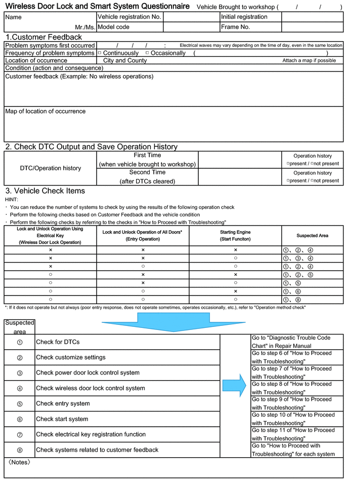
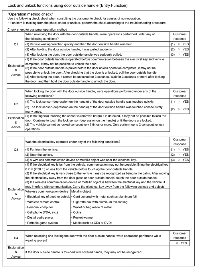
HINT:
Be sure to ask the customer in detail about the following points concerning the vehicle operating conditions, environment and problem, and then check for DTCs.
- If the entry lock/unlock function does not operate for all doors.
- If the entry lock function does not operate.
- If the entry unlock function does not operate.
- If both the entry lock and unlock functions do not operate.
- If the wireless lock and unlock functions do not operate.
- If the power source mode does not change even though the engine switch was pressed (does not change to on (ACC)).
- If the engine cannot be started with the push-button start function.
- If an engine start was attempted by holding the electrical key transmitter sub-assembly near the engine switch and then pressing the engine switch.
- If the warning buzzers inside the vehicle do not sound.
- If the warning buzzers outside the vehicle do not sound.
- If the steering wheel does not unlock.
- Any other details concerning the problem.
HINT:
If it is suspected that wave interference is likely, be sure to ask the customer in detail about the following points concerning the vehicle operating conditions, environment and problem.
- Specific locations where the system does not operate (such as near TV towers, large video displays, wireless garage door opener systems, wireless security cameras, home security systems, etc.).
- Specific times when the system does not operate: If the symptoms occurred immediately after purchase or only recently. If the symptoms occurred when the electrical key transmitter sub-assembly was near the vehicle (electrical key antenna).
- If the system does not operate only when near specific vehicles (there may be wave interference from the wireless systems of other vehicles).
- If the system operates intermittently.
- If the electrical key transmitter sub-assembly is bundled together with other items.
- If the electrical key transmitter sub-assembly is carried together with other electronic devices, such as cell phones, personal computers, portable music players, other electrical key transmitter sub-assemblies, etc. (make sure to keep the electrical key transmitter sub-assembly at least 0.1 m (0.328 ft.) away from such items).
- Where the electrical key transmitter sub-assembly is being kept when not in use: If the electrical key transmitter sub-assembly is being placed within 1 m (3.28 ft.) of items such as TVs, DVD recorders, induction cookers, rice cookers, dishwashers, modems, cell phones, personal computers, microwave ovens, desk or floor lamps, cordless telephones, etc.
- If there are electronic devices that transmit radio waves placed in the vehicle.
- When the transmitter battery was last replaced. The transmitter battery capacity can be approximated using the Key Low Battery Data List item.
Click here
.gif)
- If the customer installed any optional components (theft deterrent devices, wireless fog lights, etc.) to the vehicle.
READ NEXT:
 Operation Check
OPERATION CHECK NOTICE: Make sure that the vehicle is in an area that allows the wireless control function to operate.
HINT:
The switches described in this text are the switches for transmitting si
Customize Parameters
CUSTOMIZE PARAMETERS CUSTOMIZE WIRELESS DOOR LOCK CONTROL SYSTEM
NOTICE:
When the customer requests a change in a function, first make sure that the function can be customized.
Be sure to make a
Problem Symptoms Table
PROBLEM SYMPTOMS TABLE
HINT:
Use the table below to help determine the cause of problem symptoms. If multiple suspected areas are listed, the potential causes of the symptoms are listed in order of
SEE MORE:
USB Audio System Recognition/Play Error
DESCRIPTION When a USB device or "iPod" is connected to the USB jack of the No. 1 stereo jack adapter assembly, it must have playable files. The device must also communicate with and be recognized by the radio and display receiver assembly. This diagnostic procedure is for when a device is not recog
Right Rear Wheel Speed Sensor Supply Voltage Circuit Short to Ground or Open (C14E914)
DESCRIPTION Refer to DTC C051212 Click here
DTC No. Detection Item
DTC Detection Condition Trouble Area
C14E914 Right Rear Wheel Speed Sensor Supply Voltage Circuit Short to Ground or Open
An open or short in the speed sensor power supply circuit is detected for 0.
© 2023-2026 Copyright www.tocamry.com
