Toyota Camry (XV70): Differential Oil
Components
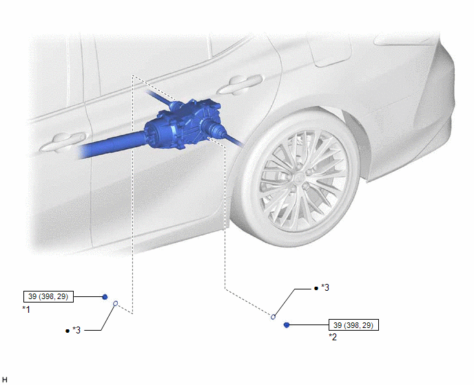
COMPONENTS
ILLUSTRATION
|
*1 | REAR DIFFERENTIAL FILLER PLUG |
*2 | REAR DIFFERENTIAL DRAIN PLUG |
|
*3 | GASKET |
- | - |
 |
N*m (kgf*cm, ft.*lbf): Specified torque |
● | Non-reusable part |
On-vehicle Inspection
ON-VEHICLE INSPECTION
PROCEDURE
1. INSPECT DIFFERENTIAL OIL
(a) Stop the vehicle on a level surface.
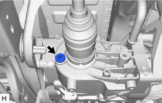
| (b) Using a 10 mm socket hexagon wrench, remove the rear differential filler plug and gasket. |
|
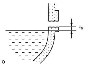
| (c) Check that the oil level is between 0 to 5 mm (0 to 0.196 in.) from the bottom lip of the differential filler plug hole. NOTICE:
|
|
(d) If there is not enough oil, inspect for oil leaks and fill the differential carrier assembly with Toyota genuine differential gear oil LT SAE 75W-85 API GL-5 or equivalent.
| (e) Using a 10 mm socket hexagon wrench, install a new gasket and the rear differential filler plug. Torque: 39 N |
READ NEXT:
 Differential System
PrecautionPRECAUTION
Before disassembling the differential assembly, thoroughly clean it by removing any sand, mud or foreign matter. This will help prevent contamination during disassembly and r
Components
COMPONENTS ILLUSTRATION
*A except 2-Pod Caliper
*B for 2-Pod Caliper
*1 FRONT AXLE ASSEMBLY
*2 FRONT AXLE SHAFT NUT
*3 FRONT DISC
*4 FRONT DISC
SEE MORE:
Customize Parameters
CUSTOMIZE PARAMETERS CUSTOMIZE WIRELESS DOOR LOCK CONTROL SYSTEM
HINT: The following items can be customized.
NOTICE:
When the customer requests a change in a function, first make sure that the function can be customized.
Be sure to make a note of the current settings before customizing.
Wh
On-vehicle Inspection
ON-VEHICLE INSPECTION PROCEDURE
1. INSPECT BRAKE BOOSTER ASSEMBLY (a) Airtightness check
(1) Start the engine and stop it after 1 or 2 minutes. Slowly depress the brake pedal several times.
If the brake pedal can be depressed nearly to the floor the first time, but on the 2nd and 3rd time
