Toyota Camry (XV70): Driver Side Door ECU Communication Stop (B2321)
DESCRIPTION
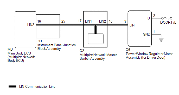
This DTC is stored when LIN communication between the power window regulator motor assembly (for driver door) and main body ECU (multiplex network body ECU) stops for 10 seconds or more.
|
DTC No. | Detection Item |
DTC Detection Condition | Trouble Area |
|---|---|---|---|
|
B2321 | Driver Side Door ECU Communication Stop |
No communication between power window regulator motor assembly (for driver door) and main body ECU (multiplex network body ECU) for 10 seconds or more. |
|
WIRING DIAGRAM
CAUTION / NOTICE / HINT
NOTICE:
- Inspect the fuses for circuits related to this system before performing the following procedure.
- When a power window regulator motor assembly is replaced or removed and reinstalled, it is necessary to perform initialization.
Click here
.gif)
- Before replacing the main body ECU (multiplex network body ECU), refer to Registration.*
Click here
- *: w/ Smart Key System
PROCEDURE
|
1. | INSPECT MULTIPLEX NETWORK MASTER SWITCH ASSEMBLY |
| (a) Remove the multiplex network master switch assembly. Click here
|
|
(b) Measure the resistance according to the value(s) in the table below.
Standard Resistance:
|
Tester Connection | Condition |
Specified Condition |
|---|---|---|
|
16 (LIN2) - 17 (LIN1) |
Always | Below 1 Ω |
| NG | .gif) | REPLACE MULTIPLEX NETWORK MASTER SWITCH ASSEMBLY |
|
.gif)
| 2. |
INSPECT INSTRUMENT PANEL JUNCTION BLOCK ASSEMBLY |
(a) Remove the instrument panel junction block assembly.
Click here
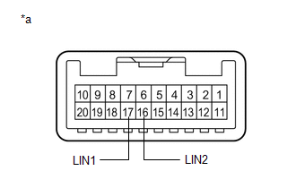
.png)
|
*a | Component without harness connected (Instrument Panel Junction Block Assembly) |
- | - |
(b) Remove the main body ECU (multiplex network body ECU) from the instrument panel junction block assembly.
(c) Measure the resistance according to the value(s) in the table below.
HINT:
This inspection is to check the LIN communication line in the instrument panel junction block assembly that connects the wire harness to the built-in main body ECU (multiplex network body ECU).
Standard Resistance:
|
Tester Connection | Condition |
Specified Condition |
|---|---|---|
|
MB-16 (LIN2) - 3D-25 |
Always | Below 1 Ω |
| NG | | REPLACE INSTRUMENT PANEL JUNCTION BLOCK ASSEMBLY
|
|
| 3. |
CHECK HARNESS AND CONNECTOR (INSTRUMENT PANEL JUNCTION BLOCK ASSEMBLY - MULTIPLEX NETWORK MASTER SWITCH ASSEMBLY) |
(a) Measure the resistance according to the value(s) in the table below.
NOTICE:
Make sure that each ECU is in sleep mode before performing the inspection. To enter sleep mode, turn the ignition switch from ON to off and wait for 180 seconds or more without operating any switches.
Standard Resistance:
|
Tester Connection | Condition |
Specified Condition |
|---|---|---|
|
3D-25 - O2-17 (LIN1) |
Ignition switch off | Below 1 Ω |
|
3D-25 or O2-17 (LIN1) - Body ground |
Ignition switch off | 10 kΩ or higher |
| NG | | REPAIR OR REPLACE HARNESS OR CONNECTOR |
|
| 4. |
CHECK HARNESS AND CONNECTOR (MULTIPLEX NETWORK MASTER SWITCH ASSEMBLY - POWER WINDOW REGULATOR MOTOR ASSEMBLY (for Driver Door)) |
(a) Disconnect the O6 power window regulator motor assembly (for driver door) connector.
(b) Measure the resistance according to the value(s) in the table below.
NOTICE:
Make sure that each ECU is in sleep mode before performing the inspection. To enter sleep mode, turn the ignition switch from ON to off and wait for 180 seconds or more without operating any switches.
Standard Resistance:
|
Tester Connection | Condition |
Specified Condition |
|---|---|---|
|
O2-16 (LIN2) - O6-9 (LIN) |
Ignition switch off | Below 1 Ω |
|
O2-16 (LIN2) or O6-9 (LIN) - Body ground |
Ignition switch off | 10 kΩ or higher |
| NG | | REPAIR OR REPLACE HARNESS OR CONNECTOR |
|
| 5. |
CHECK HARNESS AND CONNECTOR (POWER WINDOW REGULATOR MOTOR ASSEMBLY (for Driver Door) - BATTERY, BODY GROUND) |
(a) Measure the voltage according to the value(s) in the table below.
Standard Voltage:
|
Tester Connection | Condition |
Specified Condition |
|---|---|---|
|
O6-2 (B) - O6-1 (GND) |
Always | 11 to 14 V |
(b) Measure the resistance according to the value(s) in the table below.
Standard Resistance:
|
Tester Connection | Condition |
Specified Condition |
|---|---|---|
|
O6-1 (GND) - Body ground |
Always | Below 1 Ω |
| NG | | REPAIR OR REPLACE HARNESS OR CONNECTOR |
|
| 6. |
REPLACE POWER WINDOW REGULATOR MOTOR ASSEMBLY (for Driver Door) |
(a) Replace the power window regulator motor assembly (for driver door).
Click here
|
| 7. |
CHECK FOR DTC |
(a) Clear the DTCs.
Body Electrical > Main Body > Clear DTCs(b) Recheck for DTCs.
Body Electrical > Main Body > Trouble CodesOK:
DTC B2321 is not output.
| OK | | END (POWER WINDOW REGULATOR MOTOR ASSEMBLY (for Driver Door) WAS DEFECTIVE) |
| NG | | REPLACE MAIN BODY ECU (MULTIPLEX NETWORK BODY ECU)
|
READ NEXT:
 Front Passenger Side Door ECU Communication Stop (B2322)
DESCRIPTION This DTC is stored when LIN communication between the power window regulator motor assembly (for Front Passenger Door) and main body ECU (multiplex network body ECU) stops for 10 seconds o
Rear Door RH ECU Communication Stop (B2323)
DESCRIPTION This DTC is stored when LIN communication between the power window regulator motor assembly (for rear door RH) and main body ECU (multiplex network body ECU) stops for 10 seconds or more.
Rear Door LH ECU Communication Stop (B2324)
DESCRIPTION This DTC is stored when LIN communication between the power window regulator motor assembly (for rear door LH) and main body ECU (multiplex network body ECU) stops for 10 seconds or more.
SEE MORE:
Diagnostic Trouble Code Chart
DIAGNOSTIC TROUBLE CODE CHART Vehicle Stability Control System
DTC No. Detection Item
Link C00631C
Yaw Rate Sensor Circuit Voltage Out of Range
C00631F Yaw Rate Sensor Circuit Intermittent
C006396 Yaw Rate Sensor Component Internal Failure
Removal
REMOVAL CAUTION / NOTICE / HINT
The necessary procedures (adjustment, calibration, initialization or registration) that must be performed after parts are removed and installed, or replaced during fuel main valve assembly removal/installation are shown below. Necessary Procedures After Parts Remove
