Toyota Camry (XV70): Drive Mode Select Switch Circuit
DESCRIPTION
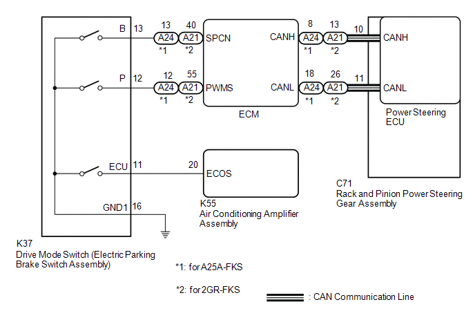
The electronic throttle and the EPS character change by the operation of the drive mode switch (electric parking brake switch assembly).
WIRING DIAGRAM
PROCEDURE
|
1. | CHECK THE PROBLEM SYMPTOMS |
(a) Check each symptom by checking the suspected areas in the table below.
|
Result | Proceed to |
|---|---|
|
SPORT mode or NORMAL mode is abnormal. |
A |
| ECO mode is abnormal. |
B |
| B | .gif) |
GO TO AIR CONDITIONING SYSTEM |
|
.gif)
|
2. | CHECK CAN COMMUNICATION SYSTEM |
(a) Check for DTCs.
Click here
.gif)
|
Result | Proceed to |
|---|---|
|
CAN communication system DTCs are not output. |
A |
| CAN communication system DTCs are output. |
B |
| B | |
GO TO CAN COMMUNICATION SYSTEM |
|
|
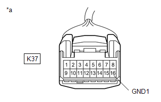
3. | CHECK HARNESS AND CONNECTOR (DRIVE MODE SWITCH (ELECTRIC PARKING BRAKE SWITCH ASSEMBLY) - BODY GROUND) |
(a) Turn the ignition switch off.
| (b) Disconnect the K37 drive mode switch (electric parking brake switch assembly) connector. |
|
(c) Measure the resistance according to the value(s) in the table below.
Standard Resistance:
|
Tester Connection | Condition |
Specified Condition |
|---|---|---|
|
K37-16 (GND1) - Body ground |
Always | Below 1 Ω |
| NG | |
REPAIR OR REPLACE HARNESS OR CONNECTOR |
|
|
4. | INSPECT DRIVE MODE SWITCH (ELECTRIC PARKING BRAKE SWITCH ASSEMBLY) |
(a) Inspect drive mode switch (electric parking brake switch assembly).
for UA80E: Click here
for UB80E: Click here
for UB80F: Click here
OK:
Drive mode switch (electric parking brake switch assembly) is normal.
|
Result | Proceed to |
|---|---|
|
CAN communication system DTCs are not output. (for A25A-FKS) |
A |
| CAN communication system DTCs are not output. (for 2GR-FKS) |
B |
| CAN communication system DTCs are output. |
C |
| B | |
GO TO STEP 6 |
| C | |
REPLACE ELECTRIC PARKING BRAKE SWITCH ASSEMBLY SWITCH ASSEMBLY for UA80E: Click here for UB80E: Click here
for UB80F: Click here
|
|
|
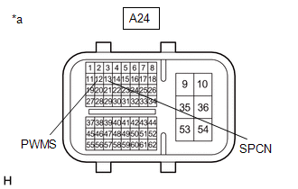
5. | CHECK HARNESS AND CONNECTOR (DRIVE MODE SWITCH (ELECTRIC PARKING BRAKE SWITCH ASSEMBLY) - ECM) |
(a) Reconnect the K37 drive mode switch (electric parking brake switch assembly) connector.
| (b) Disconnect the A24 ECM connectors. |
|
(c) Measure the resistance according to the value(s) in the table below.
Standard Resistance:
|
Tester Connection | Condition |
Specified Condition |
|---|---|---|
|
A24-12 (PWMS) - Body ground |
SPORT mode switch being turned and held |
Below 1 Ω |
|
A24-12 (PWMS) - Body ground |
SPORT mode switch not turned |
10 kΩ or higher |
|
A24-13 (SPCN) - Body ground |
NORMAL mode switch being pushed and held |
Below 1 Ω |
|
A24-13 (SPCN) - Body ground |
NORMAL mode switch not pushed |
10 kΩ or higher |
| OK | |
REPLACE ECM |
| NG | |
REPAIR OR REPLACE HARNESS OR CONNECTOR |
|
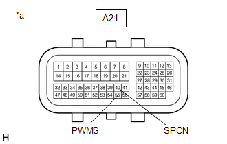
6. | CHECK HARNESS AND CONNECTOR (DRIVE MODE SWITCH (ELECTRIC PARKING BRAKE SWITCH ASSEMBLY) - ECM) |
(a) Reconnect the K37 drive mode switch (electric parking brake switch assembly) connector.
| (b) Disconnect the A21 ECM connectors. |
|
(c) Measure the resistance according to the value(s) in the table below.
Standard Resistance:
|
Tester Connection | Condition |
Specified Condition |
|---|---|---|
|
A21-55 (PWMS) - Body ground |
SPORT mode switch being turned and held |
Below 1 Ω |
| A21-55 (PWMS) - Body ground |
SPORT mode switch not turned |
10 kΩ or higher |
|
A21-40 (SPCN) - Body ground |
NORMAL mode switch being pushed and held |
Below 1 Ω |
|
A21-40 (SPCN) - Body ground |
NORMAL mode switch not pushed |
10 kΩ or higher |
| OK | |
REPLACE ECM |
| NG | |
REPAIR OR REPLACE HARNESS OR CONNECTOR |
READ NEXT:
 Precaution
PRECAUTION PRECAUTION FOR DISCONNECTING CABLE FROM NEGATIVE BATTERY TERMINAL
NOTICE: When disconnecting the cable from the negative (-) battery terminal, initialize the following system(s) after th
SEE MORE:
Reassembly
REASSEMBLY CAUTION / NOTICE / HINT
HINT:
Use the same procedure for bank 1 and bank 2.
The following procedure is for bank 2.
PROCEDURE 1. INSTALL SPARK PLUG TUBE HINT:
When using a new cylinder head LH, the spark plug tubes must be replaced.
(a) Apply adhesive to a new spark p
Dtc Check / Clear
DTC CHECK / CLEAR CHECK DTC AND FREEZE FRAME DATA (USING TECHSTREAM)
(a) Turn the ignition switch off. (b) Connect the Techstream to the DLC3.
(c) Turn the ignition switch to ON. (d) Turn the Techstream on.
(e) Enter the following menus: Chassis / Brake/EPB / Trouble Codes. Chassis > Brake
