Toyota Camry (XV70): ECM Communication Stop Mode
DESCRIPTION
|
Detection Item | Symptom |
Trouble Area |
|---|---|---|
| ECM Communication Stop Mode |
Any of the following conditions are met:
|
|
WIRING DIAGRAM
CAUTION / NOTICE / HINT
CAUTION:
When performing the confirmation driving pattern, obey all speed limits and traffic laws.
NOTICE:
- Because the order of diagnosis is important to allow correct diagnosis, make sure to begin troubleshooting using How to Proceed with Troubleshooting when CAN communication system related DTCs are output.
Click here
.gif)
- Before measuring the resistance of the CAN bus, turn the ignition switch off and leave the vehicle for 1 minute or more without operating the key or any switches, or opening or closing the doors. After that, disconnect the cable from the negative (-) battery terminal and leave the vehicle for 1 minute or more before measuring the resistance.
- After turning the ignition switch off, waiting time may be required before disconnecting the cable from the negative (-) battery terminal. Therefore, make sure to read the disconnecting the cable from the negative (-) battery terminal notices before proceeding with work.
Click here
- After performing repairs, perform the DTC check procedure and confirm that the DTCs are not output again.
DTC check procedure: Turn the ignition switch to ON and wait for 1 minute or more. Then operate the suspected malfunctioning system and drive the vehicle at 60 km/h (37 mph) or more for 5 minutes or more.
- After the repair, perform the CAN bus check and check that all the ECUs and sensors connected to the CAN communication system are displayed as normal.
Click here
- Inspect the fuses for circuits related to this system before performing the following procedure.
HINT:
- Before disconnecting related connectors for inspection, push in on each connector body to check that the connector is not loose or disconnected.
- When a connector is disconnected, check that the terminals and connector body are not cracked, deformed or corroded.
PROCEDURE
|
1. | CHECK VEHICLE TYPE |
(a) Check vehicle type.
|
Result | Proceed to |
|---|---|
|
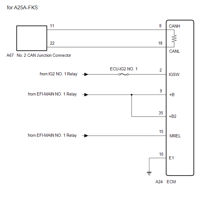
for A25A-FKS | A |
|
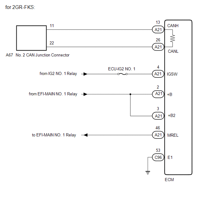
for 2GR-FKS | B |
| B |
.gif) | GO TO STEP 4 |
|
.gif)
| 2. |
CHECK FOR OPEN IN CAN BUS LINES (ECM MAIN LINE) |
(a) Disconnect the cable from the negative (-) battery terminal.
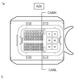
(b) Disconnect the A24 ECM connector.
| (c) Measure the resistance according to the value(s) in the table below. Standard Resistance:
|
|
| NG | | REPAIR OR REPLACE CAN MAIN BUS LINES OR CONNECTOR (ECM) |
|
| 3. |
CHECK ECM POWER SOURCE CIRCUIT |
(a) Check the ECM power source circuit.
Click here
| OK | | REPLACE ECM
|
| NG | | REPAIR OR REPLACE HARNESS OR CONNECTOR (POWER SOURCE CIRCUIT) |
| 4. |
CHECK FOR OPEN IN CAN BUS LINES (ECM MAIN LINE) |
(a) Disconnect the cable from the negative (-) battery terminal.
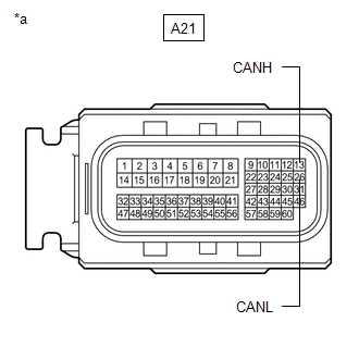
(b) Disconnect the A21 ECM connector.
| (c) Measure the resistance according to the value(s) in the table below. Standard Resistance:
|
|
| NG | | REPAIR OR REPLACE CAN MAIN BUS LINES OR CONNECTOR (ECM) |
|
| 5. |
CHECK ECM POWER SOURCE CIRCUIT |
(a) Check the ECM power source circuit.
Click here
| OK | | REPLACE ECM
|
| NG | | REPAIR OR REPLACE HARNESS OR CONNECTOR (POWER SOURCE CIRCUIT) |
READ NEXT:
 Main Body ECU Communication Stop Mode
DESCRIPTION
Detection Item Symptom
Trouble Area Main Body ECU Communication Stop Mode
Any of the following conditions are met:
Communication stop for "Main Body" is ind
Combination Meter ECU Communication Stop Mode
DESCRIPTION
Detection Item Symptom
Trouble Area Combination Meter ECU Communication Stop Mode
Any of the following conditions are met:
Communication stop for "Combinati
Certification ECU Communication Stop Mode
DESCRIPTION
Detection Item Symptom
Trouble Area Certification ECU Communication Stop Mode
Any of the following conditions are met:
Communication stop for "Certification
SEE MORE:
Installation
INSTALLATION PROCEDURE 1. INSTALL DCM (TELEMATICS TRANSCEIVER)
2. INSTALL NAVIGATION ECU (w/ Navigation System) 3. INSTALL NO. 1 TELEPHONE BRACKET
(a) w/o Navigation System: (1) Install the No. 1 telephone bracket with the screw.
(b) w/ Navigation System: (1) Install the No. 1 telephone bracke
Freeze Frame Data
FREEZE FRAME DATA DESCRIPTION The ECM records vehicle and driving condition information as freeze frame data the moment a DTC is stored. When troubleshooting, freeze frame data can be helpful in determining whether the vehicle was moving or stationary, whether the engine was warmed up or not, whethe
