
Toyota Camry (XV70): Glove Box Light
Components
COMPONENTS
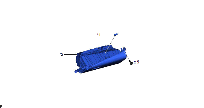
ILLUSTRATION
|
*1 | GLOVE BOX LIGHT ASSEMBLY |
*2 | LOWER INSTRUMENT PANEL SUB-ASSEMBLY |
Removal
REMOVAL
CAUTION / NOTICE / HINT
The necessary procedures (adjustment, calibration, initialization, or registration) that must be performed after parts are removed and installed, or replaced during glove box light assembly removal/installation are shown below.
Necessary Procedures After Parts Removed/Installed/Replaced|
Replaced Part or Performed Procedure |
Necessary Procedure | Effect/Inoperative Function when Necessary Procedure not Performed |
Link |
|---|---|---|---|
|
Disconnect cable from negative battery terminal |
Perform steering sensor zero point calibration |
Lane Tracing Assist System |
|
|
Pre-collision system | |||
|
Memorize steering angle neutral point |
Parking assist monitor system |
| |
|
Panoramic view monitor system |
|
CAUTION:
Some of these service operations affect the SRS airbag system. Read the precautionary notices concerning the SRS airbag system before servicing.
.png)
Click here
.gif)
PROCEDURE
1. REMOVE LOWER NO. 2 INSTRUMENT PANEL AIRBAG ASSEMBLY
Click here
2. REMOVE LOWER INSTRUMENT PANEL SUB-ASSEMBLY
Click here
3. REMOVE GLOVE BOX LIGHT ASSEMBLY
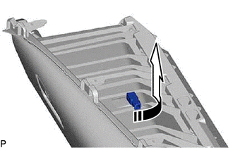
(a) Turn the glove box light assembly as shown in the illustration to remove it.
.png) |
Remove in this Direction |
Inspection
INSPECTION
PROCEDURE
1. INSPECT GLOVE BOX LIGHT ASSEMBLY
|
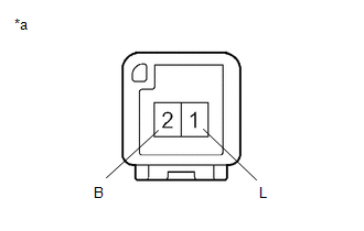
*a | Component without harness connected (Glove Box Light Assembly) |
(a) Apply battery voltage to the connector and check that the glove box light comes on.
OK:
|
Measurement Condition | Condition |
Specified Condition |
|---|---|---|
|
Battery positive (+) > 2 (B) Battery negative (-) > 1 (L) |
Always | Glove box light comes on |
If the result is not as specified, replace the glove box light assembly.
Installation
INSTALLATION
PROCEDURE
1. INSTALL GLOVE BOX LIGHT ASSEMBLY
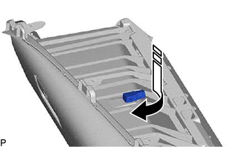
(a) Turn the glove box light assembly as shown in the illustration to install it.
.png) |
Install in this Direction |
2. INSTALL LOWER INSTRUMENT PANEL SUB-ASSEMBLY
Click here .gif)
3. INSTALL LOWER NO. 2 INSTRUMENT PANEL AIRBAG ASSEMBLY
Click here
READ NEXT:
SEE MORE:
 ABS Solenoid Control Module Actuator Stuck On (C143A7E,C143A7F,C143D49,C14DA14)
DESCRIPTION The ABS solenoid relay is built into the skid control ECU in the brake actuator assembly. The ABS solenoid relay supplies power to each solenoid.
The skid control ECU (brake actuator assembly) detects an ABS solenoid relay malfunction by performing a self check and relay operation chec
Parts Location
PARTS LOCATION ILLUSTRATION
*1 ECM
*2 ENGINE ROOM RELAY BLOCK AND JUNCTION BLOCK ASSEMBLY
- INJ FUSE *3
IGNITION COIL ASSEMBLY
*4 SPARK PLUG
