Toyota Camry (XV70): Parts Location
Toyota Camry Repair Manual XV70 (2018-2024) / Engine, Hybrid System / 2gr-fks (engine Control) / Ignition System / Parts Location
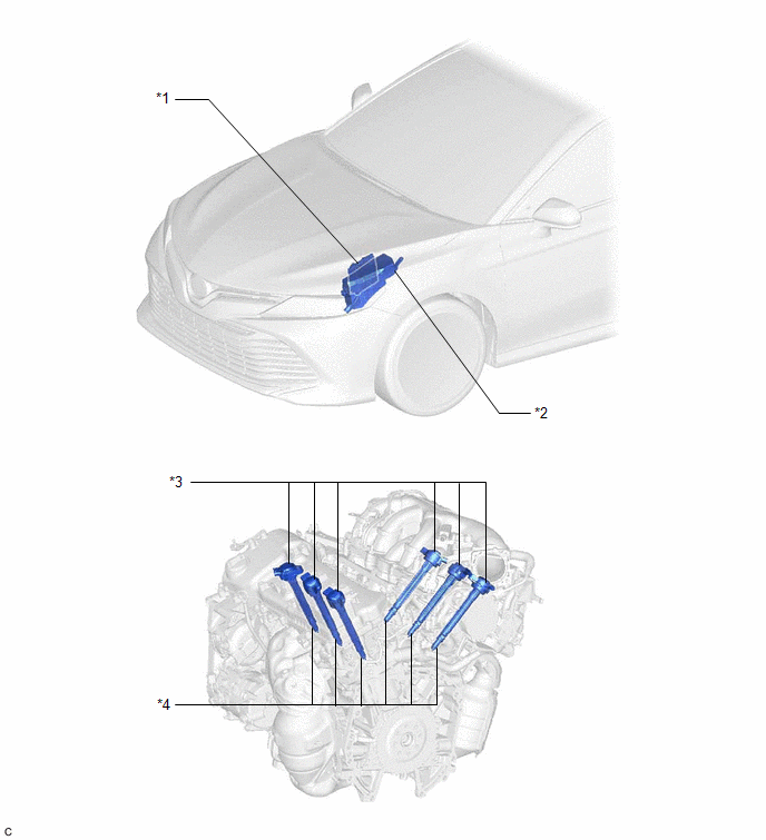
PARTS LOCATION
ILLUSTRATION
|
*1 | ECM |
*2 | ENGINE ROOM RELAY BLOCK AND JUNCTION BLOCK ASSEMBLY - INJ FUSE |
| *3 |
IGNITION COIL ASSEMBLY |
*4 | SPARK PLUG |
READ NEXT:
 System Diagram
SYSTEM DIAGRAM
On-vehicle Inspection
ON-VEHICLE INSPECTION CAUTION / NOTICE / HINT
CAUTION: To prevent injury due to contact with an operating V-ribbed belt or cooling fan, keep your hands and clothing away from the V-ribbed belt and c
SEE MORE:
Replacement
REPLACEMENT CAUTION / NOTICE / HINT
The necessary procedures (adjustment, calibration, initialization or registration) that must be performed after parts are removed and installed, or replaced during transfer case oil seal removal/installation are shown below. Necessary Procedures After Parts Remo
Problem Symptoms Table
PROBLEM SYMPTOMS TABLE
HINT:
Use the table below to help determine the cause of problem symptoms. If multiple suspected areas are listed, the potential causes of the symptoms are listed in order of probability in the "Suspected Area" column of the table. Check each symptom by checking the susp
© 2023-2026 Copyright www.tocamry.com
