Toyota Camry (XV70): System Diagram
Toyota Camry Repair Manual XV70 (2018-2024) / Engine, Hybrid System / 2gr-fks (engine Control) / Ignition System / System Diagram
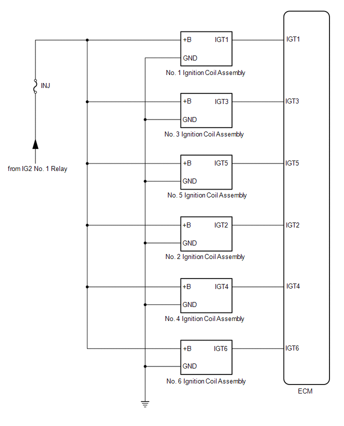
SYSTEM DIAGRAM
READ NEXT:
 On-vehicle Inspection
ON-VEHICLE INSPECTION CAUTION / NOTICE / HINT
CAUTION: To prevent injury due to contact with an operating V-ribbed belt or cooling fan, keep your hands and clothing away from the V-ribbed belt and c
Components
COMPONENTS ILLUSTRATION
*1 KNOCK CONTROL SENSOR (for Bank 1)
*2 KNOCK CONTROL SENSOR (for Bank 2)
N*m (kgf*cm, ft.*lbf): Specified torque
* For use with a un
SEE MORE:
Operation Check
OPERATION CHECK INPUT SIGNAL CHECK (a) Connect the Techstream to the DLC3.
(b) Check the cruise control main switch using the Data List function of the Techstream (cruise control main switch, -SET switch, +RES switch and CANCEL switch).
Click here INSPECT CRUISE CONTROL MAIN SWITCH
(a) Turn
Check Bus 2 Line for Short to GND
DESCRIPTION There may be a short circuit between one of the CAN bus lines and GND when there is no resistance between terminal 18 (CA4H) of the central gateway ECU (network gateway ECU) and terminal 4 (CG) of the DLC3, or terminal 17 (CA4L) of the central gateway ECU (network gateway ECU) and termin
© 2023-2026 Copyright www.tocamry.com
