Toyota Camry (XV70): Removal
REMOVAL
CAUTION / NOTICE / HINT
The necessary procedures (adjustment, calibration, initialization, or registration) that must be performed after parts are removed and installed, or replaced during front bumper assembly removal/installation are shown below.
Necessary Procedure After Parts Removed/Installed/Replaced|
Replaced Part or Performed Procedure |
Necessary Procedure | Effect/Inoperative Function when Necessary Procedure not Performed |
Link |
|---|---|---|---|
| *1: Applies only for when removing and installing or replacing the rear television camera assembly. | |||
| Front bumper assembly (w/ Panoramic view monitor system) |
Front television camera view adjustment |
Panoramic View Monitor System |
|
Replacement or removal and installation of 2 or more parts:
|
| ||
HINT:
When the front bumper is damaged or deformed due to an accident or contact with other objects, etc., or the bumper installation area on the body is repaired, it is necessary to perform millimeter wave radar sensor adjustment.
Target Adjustment (Triangle Target):
Click here
.gif)
Target Adjustment (Flat Surface Target):
Click here
Driving Adjustment:
Click here
PROCEDURE
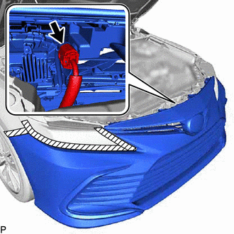
1. REMOVE COOL AIR INTAKE DUCT SEAL
| (a) Remove the 5 clips. |
|
(b) Disengage the guide and remove the cool air intake duct seal as shown in the illustration.
.png) |
Remove in this Direction (1) |
.png) |
Remove in this Direction (2) |
2. REMOVE FRONT BUMPER ASSEMBLY
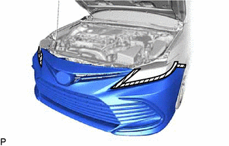
(a) Apply protective tape around the front bumper assembly as shown in the illustration.
.png) |
Protective Tape |
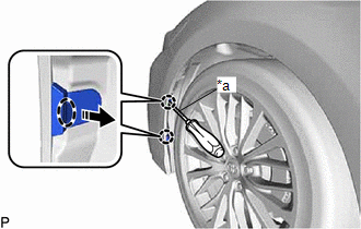
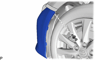
(b) Using a screwdriver with its tip wrapped with protective tape, disengage the 2 claws as shown in the illustration.
|
*a | Protective Tape |
.png) |
Insert Screwdriver Here |
|
|
Remove in this Direction |
HINT:
Use the same procedure for the RH side and LH side.
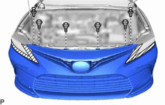
| (c) Remove the clip. HINT: Use the same procedure for the RH side and LH side. |
|
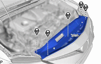
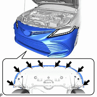
| (d) Remove the 8 screws. |
|
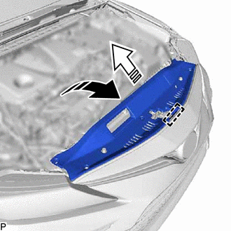
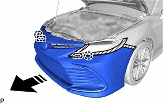
(e) Disengage the 3 claws as shown in the illustration.
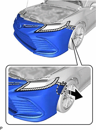
|
|
Place Hand Here |
|
|
Remove in this Direction |
HINT:
Use the same procedure for the RH side and LH side.
(f) w/ Pre-collision System:
| (1) Disconnect the connector. |
|
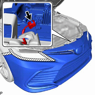
(g) w/ Parking Support Brake System:
| (1) Disconnect the connector. |
|
| (h) Remove the 2 clips. |
|
(i) Remove the 4 bolts.
(j) Disengage the 2 claws and 2 guides to remove the front bumper assembly as shown in the illustration.
|
|
Remove in this Direction |
READ NEXT:
 Disassembly
DISASSEMBLY PROCEDURE 1. REMOVE FRONT CENTER ULTRASONIC SENSOR (w/ Parking Support Brake System)
Click here 2. REMOVE FRONT CORNER ULTRASONIC SENSOR (w/ Parking Support Brake System)
Click her
Reassembly
REASSEMBLY PROCEDURE 1. INSTALL FRONT BUMPER SIDE RETAINER LH
(a) Engage the 2 clips as shown in the illustration.
Install in this Direction
(b) Install the front bum
Installation
INSTALLATION CAUTION / NOTICE / HINT
HINT:
When the front bumper is damaged or deformed due to an accident or contact with other objects, etc., or the bumper installation area on the body is
SEE MORE:
Diagnostic Trouble Code Chart
DIAGNOSTIC TROUBLE CODE CHART Electric Parking Brake System
DTC No. Detection Item
Memory Note
Link C059704
Brake System Control Module "A" System Internal Failure
DTC stored An electric parking brake system malfunction is displayed on the multi-information disp
ABS Warning Light does not Come ON
DESCRIPTION The skid control ECU (brake actuator assembly) controls the ABS warning light in the combination meter assembly via CAN communication. CAUTION / NOTICE / HINT
NOTICE: After replacing the skid control ECU (brake actuator assembly), perform acceleration sensor zero point calibration and
