Toyota Camry (XV70): Components
COMPONENTS
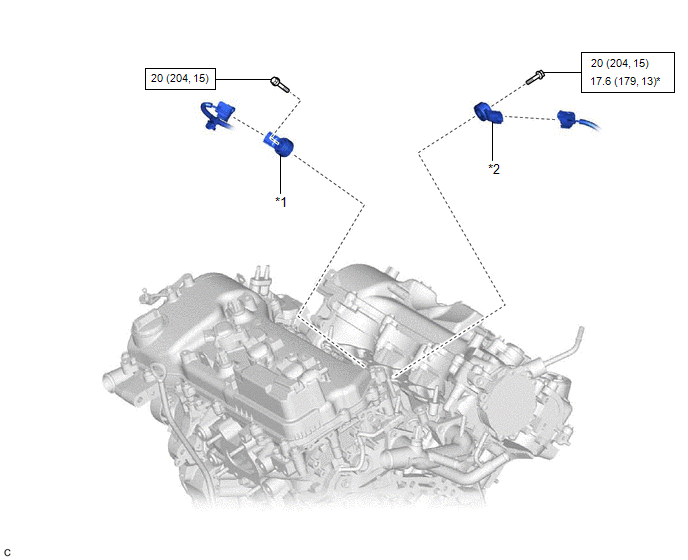
ILLUSTRATION
|
*1 | KNOCK CONTROL SENSOR (for Bank 1) |
*2 | KNOCK CONTROL SENSOR (for Bank 2) |
.png) |
N*m (kgf*cm, ft.*lbf): Specified torque |
* | For use with a union nut wrench |
READ NEXT:
 Removal
REMOVAL CAUTION / NOTICE / HINT
The necessary procedures (adjustment, calibration, initialization or registration) that must be performed after parts are removed and installed, or replaced during kn
Inspection
INSPECTION PROCEDURE 1. INSPECT KNOCK CONTROL SENSOR
(a) Measure the resistance according to the value(s) in the table below.
Standard Resistance:
Tester Connection Condition
Installation
INSTALLATION PROCEDURE 1. INSTALL KNOCK CONTROL SENSOR
HINT: Perform "Inspection After Repair" after replacing a knock control sensor.
Click here
(a) Temporarily install the 2 knock contro
SEE MORE:
Installation
INSTALLATION PROCEDURE 1. INSTALL CAMSHAFT TIMING OIL CONTROL SOLENOID ASSEMBLY (for Intake Side of Bank 2)
(a) Apply engine oil to a new O-ring and install it to the camshaft timing oil control solenoid assembly as shown in the illustration.
NOTICE: Do not damage the O-ring.
Portable Player cannot be Registered
CAUTION / NOTICE / HINT HINT: Some versions of "Bluetooth" compatible audio players may not function properly, or the functions may be limited using the radio and display receiver assembly, even if the portable audio player itself can play files.
Click here
PROCEDURE
1.
CHECK T
© 2023-2026 Copyright www.tocamry.com
