Toyota Camry (XV70): Installation
INSTALLATION
PROCEDURE
1. INSTALL KNOCK CONTROL SENSOR
HINT:
Perform "Inspection After Repair" after replacing a knock control sensor.
Click here .gif)
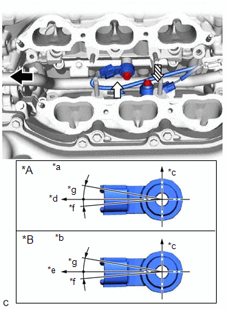
(a) Temporarily install the 2 knock control sensors to the cylinder block sub-assembly with the 2 bolts so that the knock control sensor installation position is as shown in the illustration.
|
*A | for Bank 1 |
|
*B | for Bank 2 |
|
*a | View A |
|
*b | View B |
|
*c | Top |
|
*d | Engine Front |
|
*e | Engine Rear |
|
*f | 5° |
|
*g | 10° |
.png) |
Engine Front |
.png) |
View A |
 |
View B |
NOTICE:
- If a knock control sensor has been struck or dropped, replace it.
- Make sure that the knock control sensor is installed in the correct position.
| (b) Tighten the bolt (A). Torque: 20 N·m {204 kgf·cm, 15 ft·lbf} |
|
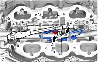
(c) Using a 10 mm union nut wrench, tighten the bolt (B).
Torque:
Specified tightening torque :
20 N·m {204 kgf·cm, 15 ft·lbf}
HINT:
- Calculate the torque wrench reading when changing the fulcrum length of the torque wrench.
Click here
- When using a 10 mm union nut wrench (fulcrum length of 22 mm (0.866 in.)) + torque wrench (fulcrum length of 162 mm (6.38 in.)):
17.6 N*m (179 kgf*cm, 13 ft.*lbf)
(d) Connect the 2 knock control sensor connectors.
2. INSTALL FUEL DELIVERY PIPE
Click here
3. PERFORM INITIALIZATION
(a) Perform "Inspection After Repair" after replacing a knock control sensor.
Click here
READ NEXT:
 Components
COMPONENTS ILLUSTRATION
*1 MASS AIR FLOW METER SUB-ASSEMBLY
- -
On-vehicle Inspection
ON-VEHICLE INSPECTION PROCEDURE
1. INSPECT MASS AIR FLOW METER SUB-ASSEMBLY HINT: Perform "Inspection After Repair" after replacing the mass air flow meter sub-assembly.
Click here
(a) Rea
SEE MORE:
Data List / Active Test
DATA LIST / ACTIVE TEST DATA LIST HINT:
Using the Techstream to read the Data List allows the values or states of switches, sensors, actuators and other items to be read without removing any parts. This non-intrusive inspection can be very useful because intermittent conditions or signals may be d
Inspection
INSPECTION PROCEDURE 1. INSPECT HEADLIGHT ASSEMBLY LH (for Bulb Type Turn Signal Light)
*a Component without harness connected
(Headlight Assembly LH) (a) Apply battery voltage to the headlight assembly LH and check that the Lo/Hi beam shade operates.
OK:
Condition
