Toyota Camry (XV70): Inspection
INSPECTION
PROCEDURE
1. INSPECT KNOCK CONTROL SENSOR
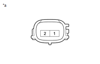
| (a) Measure the resistance according to the value(s) in the table below. Standard Resistance:
If the result is not as specified, replace the knock control sensor. |
|
READ NEXT:
 Installation
INSTALLATION PROCEDURE 1. INSTALL KNOCK CONTROL SENSOR
HINT: Perform "Inspection After Repair" after replacing a knock control sensor.
Click here
(a) Temporarily install the 2 knock contro
Components
COMPONENTS ILLUSTRATION
*1 MASS AIR FLOW METER SUB-ASSEMBLY
- -
SEE MORE:
Steering Pad Switch Circuit
DESCRIPTION
The steering pad switch assembly outputs the on/off signal and various control signals to the ECM.
The ECM performs cruise control according to the signals received from the steering pad switch assembly.
WIRING DIAGRAM for A25A-FKS
for 2GR-FKS
CAUTION / NOTICE / HINT
Parts Location
PARTS LOCATION ILLUSTRATION
*1 FRONT ENGINE MOUNTING INSULATOR
*2 REAR ENGINE MOUNTING INSULATOR
*3 CANISTER
*4 FUEL PUMP (for Low Pressure Side)
*5 MASS AIR FLOW METER SUB-ASSEMBLY
*6 PARK / NEUTRAL POSITION SWITCH ASSEMBLY
*7 VACUUM
© 2023-2026 Copyright www.tocamry.com
