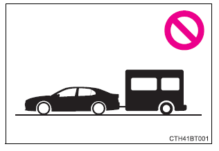
Toyota Camry (XV70): Trailer towing
Toyota does not recommend towing a trailer with your vehicle.
Toyota also does not recommend the installation of a tow hitch or the use of a tow hitch carrier for a wheelchair, scooter, bicycle, etc. Your vehicle is not designed for trailer towing or for the use of tow hitch mounted carriers.
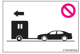
Dinghy towing
Your vehicle is not designed to be dinghy towed (with 4 wheels on the ground) behind a motor home.
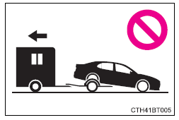
NOTICE
■To avoid serious damage to your vehicle
Do not tow your vehicle with four wheels on the ground.
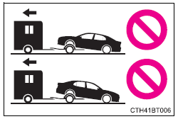
■To prevent causing serious damage to the transmission (2WD models)
Never tow this vehicle from the rear with the front wheels on the ground.
This may cause serious damage to the transmission.
■To prevent causing serious damage to the transmission and AWD system (AWD models)
Never tow this vehicle with any of the wheels on the ground.
This may cause serious damage to the transmission and AWD system.
READ NEXT:
 Engine (ignition) switch
(vehicles without a
smart key system)
Engine (ignition) switch
(vehicles without a
smart key system)
Starting the engine
1. Check that the parking brake is set.
2. Check that the shift lever is in P.
3. Firmly depress the brake pedal.
4. Turn the engine switch to the "START" position and start th
Engine (ignition) switch
(vehicles with a
smart key system)
Performing the following operations when carrying the electronic
key on your person starts the engine or changes engine
switch modes.
Starting the engine
1. Check that the parking brake is set.
2
SEE MORE:
Inspection
INSPECTION PROCEDURE 1. INSPECT ENGINE OIL LEVEL SENSOR
(a) Measure the resistance according to the value(s) in the table below.
Standard Resistance:
Tester Connection Condition
Specified Condition
1 - Body ground ON
Below 1 Ω
OFF 10 kΩ
Lost Communication with ECM/PCM "A" Missing Message (U010087,U012587,U012687,U012987,U013187,U015587)
DESCRIPTION When a malfunction is detected between various ECUs and sensors, these DTCs are stored.
DTC No. Detection Item
DTC Detection Condition Trouble Area
U010087 Lost Communication with ECM/PCM "A" Missing Message
After 3 seconds or more have elapsed since turnin
