Toyota Camry (XV70): Removal
REMOVAL
CAUTION / NOTICE / HINT
The necessary procedures (adjustment, calibration, initialization or registration) that must be performed after parts are removed and installed, or replaced during knock control sensor removal/installation are shown below.
Necessary Procedures After Parts Removed/Installed/Replaced|
Replaced Part or Performed Procedure |
Necessary Procedure | Effect/Inoperative Function when Necessary Procedure not Performed |
Link |
|---|---|---|---|
|
Battery terminal is disconnected/reconnected |
Perform steering sensor zero point calibration |
Lane Tracing Assist System |
|
|
Pre-collision System | |||
|
Memorize steering angle neutral point |
Parking Assist Monitor System |
| |
|
Panoramic View Monitor System |
| ||
| Inspection after repair |
|
|
PROCEDURE
1. REMOVE FUEL DELIVERY PIPE
Click here
.gif)
2. REMOVE KNOCK CONTROL SENSOR
| (a) Disconnect the 2 knock control sensor connectors. |
|
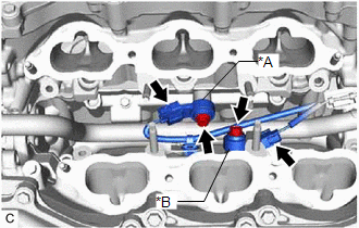
(b) Remove the 2 bolts and 2 knock control sensors from the cylinder block sub-assembly.
NOTICE:
If a knock control sensor has been struck or dropped, replace it.
READ NEXT:
 Inspection
INSPECTION PROCEDURE 1. INSPECT KNOCK CONTROL SENSOR
(a) Measure the resistance according to the value(s) in the table below.
Standard Resistance:
Tester Connection Condition
Installation
INSTALLATION PROCEDURE 1. INSTALL KNOCK CONTROL SENSOR
HINT: Perform "Inspection After Repair" after replacing a knock control sensor.
Click here
(a) Temporarily install the 2 knock contro
SEE MORE:
Components
COMPONENTS ILLUSTRATION
*1 REAR ENGINE UNDER COVER LH
*2 FRONT FENDER APRON SEAL LH
*3 NO. 1 ENGINE UNDER COVER
*4 FRONT WHEEL OPENING EXTENSION PAD LH
*5 FRONT WHEEL OPENING EXTENSION PAD RH
- -
N*m (kgf*cm, ft.*lbf): Specified
Removal
REMOVAL CAUTION / NOTICE / HINT
The necessary procedures (adjustment, calibration, initialization or registration) that must be performed after parts are removed and installed, or replaced during door control and tire pressure warning ECU and receiver or electrical key and tire pressure warning EC
