Toyota Camry (XV70): Removal
REMOVAL
CAUTION / NOTICE / HINT
The necessary procedures (adjustment, calibration, initialization, or registration) that must be performed after parts are removed and installed, or replaced during rear axle carrier sub-assembly removal/installation are shown below.
Necessary Procedures After Parts Removed/Installed/Replaced|
Replaced Part or Performed Procedure |
Necessary Procedure | Effect/Inoperative Function when Necessary Procedure not Performed |
Link |
|---|---|---|---|
| Rear wheel alignment adjustment |
|
|
|
|
Suspension, tires, etc. (The vehicle height changes because of suspension or tire replacement) |
Rear television camera assembly optical axis (Back camera position setting) |
Parking assist monitor system |
|
| Panoramic view monitor system |
|
HINT:
- Use the same procedure for the RH side and LH side.
- The following procedure is for the LH side.
PROCEDURE
1. REMOVE REAR WHEEL
Click here
.gif)
2. REMOVE NO. 2 FLOOR UNDER COVER (for LH Side)
Click here
3. REMOVE NO. 1 FLOOR UNDER COVER (for RH Side)
Click here
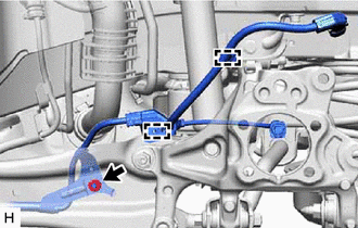
4. SEPARATE NO. 2 PARKING BRAKE WIRE ASSEMBLY
| (a) Disconnect the No. 2 parking brake wire assembly connector from the parking brake actuator assembly. NOTICE:
|
|
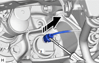
| (b) Using a screwdriver with its tip wrapped with protective tape, disconnect the No. 2 parking brake wire assembly connector from the rear axle hub and bearing assembly. NOTICE: Be careful not to damage the rear axle hub and bearing assembly or connector cover. |
|
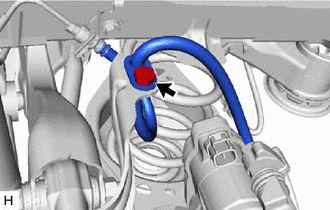
| (c) Remove the nut, disengage the 2 clamps and separate the No. 2 parking brake wire assembly from the rear flexible hose bracket and rear trailing arm assembly. |
|
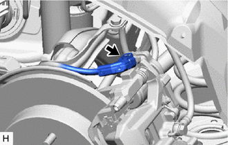
5. SEPARATE REAR FLEXIBLE HOSE
| (a) Remove the bolt and separate the rear flexible hose from the rear flexible hose bracket. |
|
6. SEPARATE REAR DISC BRAKE CALIPER ASSEMBLY
Click here
7. REMOVE REAR DISC
Click here
8. REMOVE REAR AXLE HUB AND BEARING ASSEMBLY
Click here
9. REMOVE REAR FLEXIBLE HOSE BRACKET
| (a) Remove the bolt and rear flexible hose bracket from the rear axle carrier sub-assembly. |
|
10. REMOVE REAR STABILIZER LINK ASSEMBLY
Click here
11. REMOVE REAR COIL SPRING
Click here
12. REMOVE REAR LOWER COIL SPRING INSULATOR
Click here
13. REMOVE REAR NO. 1 SUSPENSION ARM ASSEMBLY
Click here
14. REMOVE REAR AXLE CARRIER SUB-ASSEMBLY
| (a) Loosen the 2 bolts of the rear trailing arm assembly. |
|

| (b) Loosen the nut of the rear shock absorber assembly. NOTICE: Hold the rear axle carrier pin while rotating the nut. |
|
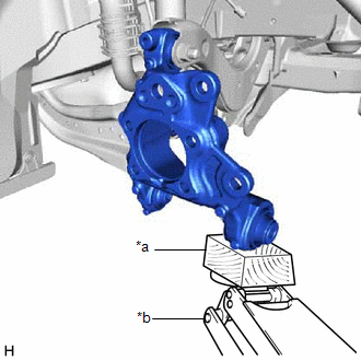
| (c) Using a jack and a wooden block, support the rear axle carrier sub-assembly. NOTICE:
|
|
| (d) Loosen the bolt (A). NOTICE: Because the nut has its own stopper, do not turn the nut. Loosen the bolt with the nut secured. |
|
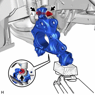
(e) Remove the 2 bolts and separate the rear trailing arm assembly from the rear axle carrier sub-assembly.
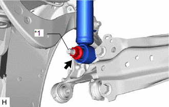
(f) Remove the nut and plate washer, and separate the rear shock absorber assembly from the rear axle carrier sub-assembly.
NOTICE:
Hold the rear axle carrier pin while rotating the nut.
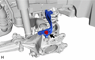
(g) Remove the bolt (A), nut and rear axle carrier sub-assembly from the rear upper control arm assembly.
NOTICE:
Because the nut has its own stopper, do not turn the nut. Loosen the bolt with the nut secured.
READ NEXT:
 Installation
INSTALLATION CAUTION / NOTICE / HINT
HINT:
Use the same procedure for the RH side and LH side.
The following procedure is for the LH side.
PROCEDURE 1. TEMPORARILY INSTALL REAR AXLE CARR
Components
COMPONENTS ILLUSTRATION
*A for RH Side
*B for LH Side
*1 NO. 1 FLOOR UNDER COVER
*2 NO. 2 FLOOR UNDER COVER
N*m (kgf*cm, ft.*lbf): Specified torque
SEE MORE:
Dtc Check / Clear
DTC CHECK / CLEAR NOTICE: When the diagnosis system is changed from normal mode to check mode or vice versa, all DTCs and freeze frame data recorded in normal mode are cleared. Before changing modes, always check and make a note of DTCs and freeze frame data.
HINT:
DTCs which are stored in the
Problem Symptoms Table
PROBLEM SYMPTOMS TABLE
HINT:
Use the table below to help determine the cause of problem symptoms. If multiple suspected areas are listed, the potential causes of the symptoms are listed in order of probability in the "Suspected Area" column of the table. Check each symptom by checking the susp
