Toyota Camry (XV70): Installation
INSTALLATION
CAUTION / NOTICE / HINT
HINT:
- Use the same procedure for the RH side and LH side.
- The following procedure is for the LH side.
PROCEDURE
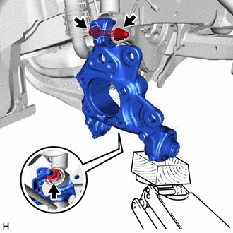
1. TEMPORARILY INSTALL REAR AXLE CARRIER SUB-ASSEMBLY
(a) Temporarily install the rear axle carrier sub-assembly to the rear shock absorber assembly with the nut and plate washer.
NOTICE:
Hold the rear axle carrier pin while rotating the nut.
| (b) Temporarily install the rear axle carrier sub-assembly to the rear upper control arm assembly with the bolt and nut. NOTICE:
|
|
(c) Install the rear trailing arm assembly to the rear axle carrier sub-assembly with the 2 bolts.
Torque:
135 N
READ NEXT:
 Components
COMPONENTS ILLUSTRATION
*A for RH Side
*B for LH Side
*1 NO. 1 FLOOR UNDER COVER
*2 NO. 2 FLOOR UNDER COVER
N*m (kgf*cm, ft.*lbf): Specified torque
Removal
REMOVAL CAUTION / NOTICE / HINT
The necessary procedures (adjustment, calibration, initialization, or registration) that must be performed after parts are removed and installed, or replaced during r
SEE MORE:
Reassembly
REASSEMBLY CAUTION / NOTICE / HINT
HINT:
Use the same procedure for the RH side and LH side.
The following procedure is for the LH side.
PROCEDURE 1. INSTALL REAR DOOR WINDOW FRAME MOULDING SUB-ASSEMBLY
Click here 2. INSTALL REAR DOOR FRONT OUTSIDE SEAL
(a) Engage the
Front passenger occupant classification system
Your vehicle is equipped with a front passenger occupant classification
system. This system detects the conditions of the front
passenger seat and activates or deactivates the front passenger
airbag and front passenger knee airbag.
Driver's and front passenger's seat belt reminder light
S
© 2023-2026 Copyright www.tocamry.com
