
Toyota Camry (XV70): Inside Handle Illumination Light Circuit
DESCRIPTION
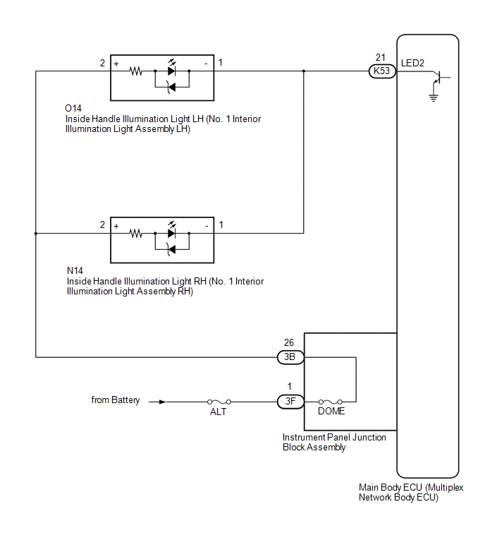
The main body ECU (multiplex network body ECU) controls the operation of the following lights:
- Inside Handle Illumination Light LH (No. 1 Interior Illumination Light Assembly LH)
- Inside Handle Illumination Light RH (No. 1 Interior Illumination Light Assembly RH)
WIRING DIAGRAM
CAUTION / NOTICE / HINT
NOTICE:
- Inspect the fuses for circuits related to this system before performing the following procedure.
- Before replacing the main body ECU (multiplex network body ECU), refer to Registration.*
Click here

- *: w/ Smart Key System
PROCEDURE
|
1. | PERFORM ACTIVE TEST USING TECHSTREAM |
(a) Connect the Techstream to the DLC3.
(b) Turn the ignition switch to ON.
(c) Turn the Techstream on.
(d) Enter the following menus: Body Electrical / Main Body / Active Test.
(e) Perform the Active Test according to the display on the Techstream.
Body Electrical > Main Body > Active Test|
Tester Display | Measurement Item |
Control Range | Diagnostic Note |
|---|---|---|---|
|
Interior Illumination Light2 |
Inside handle illumination light (No. 1 interior illumination light assembly) |
OFF or ON | Preconditions for using the Active Test to check dimmer controlled illumination:
|
|
Tester Display |
|---|
| Interior Illumination Light2 |
OK:
Inside handle illumination lights come on.
|
Result | Proceed to |
|---|---|
|
OK | A |
|
NG (Inside handle illumination light LH does not come on) |
B |
| NG (Inside handle illumination light RH does not come on) |
C |
| NG (Inside handle illumination light LH and RH do not come on) |
D |
| A |
 | USE SIMULATION METHOD TO CHECK
|
| C |
| GO TO STEP 5 |
| D |
| GO TO STEP 8 |
|

| 2. |
INSPECT NO. 1 INTERIOR ILLUMINATION LIGHT ASSEMBLY LH |
(a) Remove the inside handle illumination light LH (No. 1 interior illumination light assembly LH).
Click here
(b) Inspect the inside handle illumination light LH (No. 1 interior illumination light assembly LH).
Click here
| NG | | REPLACE INSIDE HANDLE ILLUMINATION LIGHT LH (NO. 1 INTERIOR ILLUMINATION LIGHT ASSEMBLY LH)
|
|
| 3. |
CHECK HARNESS AND CONNECTOR (INSTRUMENT PANEL JUNCTION BLOCK ASSEMBLY - NO. 1 INTERIOR ILLUMINATION LIGHT ASSEMBLY LH) |
(a) Disconnect the 3B instrument panel junction block assembly connector.
(b) Measure the resistance according to the value(s) in the table below.
Standard Resistance:
|
Tester Connection | Condition |
Specified Condition |
|---|---|---|
|
3B-26 - O14-2 (+) | Always |
Below 1 ? |
| NG | | REPAIR OR REPLACE HARNESS OR CONNECTOR |
|
| 4. |
CHECK HARNESS AND CONNECTOR (NO. 1 INTERIOR ILLUMINATION LIGHT ASSEMBLY LH - MAIN BODY ECU (MULTIPLEX NETWORK BODY ECU)) |
(a) Disconnect the K53 main body ECU (multiplex network body ECU) connector.
(b) Measure the resistance according to the value(s) in the table below.
Standard Resistance:
|
Tester Connection | Condition |
Specified Condition |
|---|---|---|
|
O14-1 (-) - K53-21 (LED2) |
Always | Below 1 ? |
| OK | | USE SIMULATION METHOD TO CHECK
|
| NG | | REPAIR OR REPLACE HARNESS OR CONNECTOR |
| 5. |
INSPECT NO. 1 INTERIOR ILLUMINATION LIGHT ASSEMBLY RH |
(a) Remove the inside handle illumination light RH (No. 1 interior illumination light assembly RH).
Click here
(b) Inspect the inside handle illumination light RH (No. 1 interior illumination light assembly RH).
Click here
| NG | | REPLACE INSIDE HANDLE ILLUMINATION LIGHT RH (NO. 1 INTERIOR ILLUMINATION LIGHT ASSEMBLY RH)
|
|
| 6. |
CHECK HARNESS AND CONNECTOR (INSTRUMENT PANEL JUNCTION BLOCK ASSEMBLY - NO. 1 INTERIOR ILLUMINATION LIGHT ASSEMBLY RH) |
(a) Disconnect the 3B instrument panel junction block assembly connector.
(b) Measure the resistance according to the value(s) in the table below.
Standard Resistance:
|
Tester Connection | Condition |
Specified Condition |
|---|---|---|
|
3B-26 - N14-2 (+) | Always |
Below 1 ? |
| NG | | REPAIR OR REPLACE HARNESS OR CONNECTOR |
|
| 7. |
CHECK HARNESS AND CONNECTOR (NO. 1 INTERIOR ILLUMINATION LIGHT ASSEMBLY RH - MAIN BODY ECU (MULTIPLEX NETWORK BODY ECU)) |
(a) Disconnect the K53 main body ECU (multiplex network body ECU) connector.
(b) Measure the resistance according to the value(s) in the table below.
Standard Resistance:
|
Tester Connection | Condition |
Specified Condition |
|---|---|---|
|
N14-1 (-) - K53-21 (LED2) |
Always | Below 1 ? |
| OK | | USE SIMULATION METHOD TO CHECK
|
| NG | | REPAIR OR REPLACE HARNESS OR CONNECTOR |
| 8. |
CHECK HARNESS AND CONNECTOR (POWER SOURCE - INSTRUMENT PANEL JUNCTION BLOCK ASSEMBLY) |
(a) Disconnect the 3F instrument panel junction block assembly connector.
(b) Measure the voltage according to the value(s) in the table below.
Standard Voltage:
|
Tester Connection | Condition |
Specified Condition |
|---|---|---|
|
3F-1 - Body ground | Always |
11 to 14 V |
| NG | | REPAIR OR REPLACE HARNESS OR CONNECTOR |
|
| 9. |
CHECK INSTRUMENT PANEL JUNCTION BLOCK ASSEMBLY |
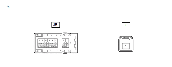
|
*a | Component without harness connected (Instrument Panel Junction Block Assembly) |
- | - |
(a) Disconnect the 3B instrument panel junction block assembly connector.
(b) Measure the resistance according to the value(s) in the table below.
Standard Resistance:
|
Tester Connection | Condition |
Specified Condition |
|---|---|---|
|
3B-26 - 3F-1 | Always |
Below 1 ? |
| NG | | REPLACE INSTRUMENT PANEL JUNCTION BLOCK ASSEMBLY
|
|
| 10. |
CHECK HARNESS AND CONNECTOR (INSTRUMENT PANEL JUNCTION BLOCK ASSEMBLY - NO. 1 INTERIOR ILLUMINATION LIGHT ASSEMBLY) |
(a) Disconnect the O14 inside handle illumination light LH (No. 1 interior illumination light assembly LH) connector.
(b) Disconnect the N14 inside handle illumination light RH (No. 1 interior illumination light assembly RH) connector.
(c) Measure the resistance according to the value(s) in the table below.
Standard Resistance:
|
Tester Connection | Condition |
Specified Condition |
|---|---|---|
|
3B-26 - O14-2 (+) | Always |
Below 1 ? |
|
3B-26 - N14-2 (+) | Always |
Below 1 ? |
|
3B-26, O14-2 (+) or N14-2 (+) - Body ground |
Always | 10 k? or higher |
| NG | | REPAIR OR REPLACE HARNESS OR CONNECTOR |
|
| 11. |
CHECK HARNESS AND CONNECTOR (NO. 1 INTERIOR ILLUMINATION LIGHT ASSEMBLY - MAIN BODY ECU (MULTIPLEX NETWORK BODY ECU)) |
(a) Disconnect the K53 main body ECU (multiplex network body ECU) connector.
(b) Measure the resistance according to the value(s) in the table below.
Standard Resistance:
|
Tester Connection | Condition |
Specified Condition |
|---|---|---|
|
O14-1 (-) - K53-21 (LED2) |
Always | Below 1 ? |
|
N14-1 (-) - K53-21 (LED2) |
Always | Below 1 ? |
|
O14-1 (-), N14-1 (-) or K53-21 (LED2) - Body ground |
Always | 10 k? or higher |
| OK | | REPLACE MAIN BODY ECU (MULTIPLEX NETWORK BODY ECU)
|
| NG | | REPAIR OR REPLACE HARNESS OR CONNECTOR |
READ NEXT:
SEE MORE:
 Slip Indicator Light Remains ON
DESCRIPTION This procedure is for troubleshooting when the slip indicator light remains on but no DTCs are output.
The skid control ECU (brake actuator assembly) controls the slip indicator light in the combination meter assembly via CAN communication.
The slip indicator light blinks during VSC
Installation
INSTALLATION PROCEDURE 1. INSTALL LOWER RADIATOR SUPPORT
(a) Install the 2 lower radiator supports to the radiator assembly. 2. INSTALL RADIATOR SUPPORT CUSHION
(a) Install the 2 radiator support cushions to the radiator assembly. 3. INSTALL RADIATOR ASSEMBLY
(a) Engage the 2 guides. (b) Engag
