Toyota Camry (XV70): Inspection
INSPECTION
PROCEDURE
1. INSPECT COMBINATION SWITCH (ELECTRIC PARKING BRAKE SWITCH ASSEMBLY)
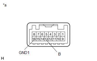
(a) Inspect the NORMAL mode switch:
| (1) Measure the resistance according to the value(s) in the table below. Standard Resistance:
If the result is not as specified, replace the combination switch (electric parking brake switch assembly). |
|
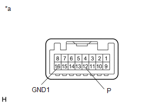
(b) Inspect the SPORT mode switch:
| (1) Measure the resistance according to the value(s) in the table below. Standard Resistance:
If the result is not as specified, replace the combination switch (electric parking brake switch assembly). |
|
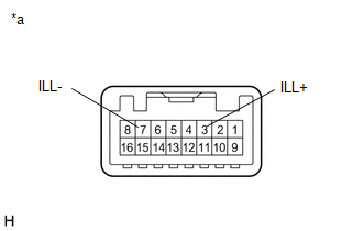
(c) Inspect the illumination:
| (1) Apply battery voltage to the combination switch (electric parking brake switch assembly) and check that the switch illuminates. OK:
If the result is not as specified, replace the combination switch (electric parking brake switch assembly). |
|
READ NEXT:
 Installation
INSTALLATION PROCEDURE 1. INSTALL COMBINATION SWITCH (ELECTRIC PARKING BRAKE SWITCH ASSEMBLY)
Click here 2. INSTALL REAR UPPER CONSOLE PANEL SUB-ASSEMBLY
Click here
3. INSTALL SHIFT LEVE
Components
COMPONENTS ILLUSTRATION
*1 FRONT DIFFERENTIAL CASE FRONT TAPERED ROLLER BEARING (INNER RACE)
*2 FRONT DIFFERENTIAL CASE FRONT TAPERED ROLLER BEARING (OUTER RACE)
*3 FRONT
SEE MORE:
System Diagram
SYSTEM DIAGRAM FUEL FLOW DIAGRAM
*A for Direct Injection
- -
*1 Fuel Injector Assembly
*2 Throttle Body with Motor Assembly
*3 Fuel Pressure Sensor (Fuel Delivery Pipe with Sensor Assembly LH) (for High Pressure)
*4 Fuel Pressure Pulsation Damp
How To Proceed With Troubleshooting
CAUTION / NOTICE / HINT
HINT:
Use the following procedure to troubleshoot the power mirror control system
*: Use the Techstream.
PROCEDURE
1. VEHICLE BROUGHT TO WORKSHOP
NEXT
2. CUSTOMER PROBLEM ANALYSIS
HINT:
