Toyota Camry (XV70): Inspection
INSPECTION
PROCEDURE
1. INSPECT FUEL LID OPENER SWITCH
| (a) Check the switch. (1) Measure the resistance according to the value(s) in the table below. Standard Resistance:
If the result is not as specified, replace the fuel lid opener switch. |
|
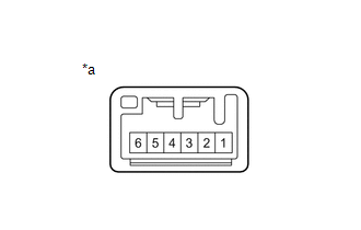
(b) Check the switch illumination.
(1) Apply battery voltage to the switch connector and check that the fuel lid opener switch illuminates.
OK:
|
Battery Condition | Specified Condition |
|---|---|
|
Battery positive (+) → Terminal 6 Battery negative (-) → Terminal 1 |
Illumination illuminates |
If the result is not as specified, replace the fuel lid opener switch.
READ NEXT:
 Installation
INSTALLATION PROCEDURE 1. INSTALL FUEL LID OPENER SWITCH
(a) Engage the 2 claws to install the fuel lid opener switch as shown in the illustration.
Install in this Direction
Precaution
PRECAUTION PRECAUTION FOR DISCONNECTING CABLE FROM NEGATIVE BATTERY TERMINAL
NOTICE: When disconnecting the cable from the negative (-) battery terminal, initialize the following systems after the
SEE MORE:
Air outlets - Automatic air conditioning system (with "SYNC" button)
â– Location of air outlets
The air outlets and air volume
change according to the
selected airflow mode.
â– Adjusting the position of and opening and closing the air outlets
Front
Rear
Direct air flow to the left or right, up or down.
Turn the knob to open or close the vent.
â
Parts Location
PARTS LOCATION ILLUSTRATION
*1 FUEL SENDER GAUGE ASSEMBLY
*2 FUEL PUMP (for Low Pressure)
*3 FUEL PUMP CONTROL ECU
*4 FUEL TANK ASSEMBLY
*5 FUEL SUCTION TUBE WITH PUMP AND GAUGE ASSEMBLY
*6 FUEL MAIN VALVE ASSEMBLY (for Low Pressure)
*7
© 2023-2026 Copyright www.tocamry.com
