
Toyota Camry (XV70): Inspection
INSPECTION
PROCEDURE
1. INSPECT AUTO HIGH BEAM SWITCH
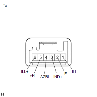
|
*a | Component without harness connected (Auto High Beam Switch) |
(a) Measure the resistance according to the value(s) in the table below.
Standard Resistance:
|
Tester Connection | Condition |
Specified Condition |
|---|---|---|
|
5 (+B) - 2 (E) | Auto high beam switch not pressed |
10 kΩ or higher |
|
Auto high beam switch pressed |
Below 1 Ω |
If the result is not as specified, replace the auto high beam switch.
(b) Illumination Inspection
(1) Apply battery voltage to the auto high beam switch and check that the switch illuminates.
OK:
|
Condition | Specified Condition |
|---|---|
|
Battery positive (+) → Terminal 6 (ILL+) Battery negative (-) → Terminal 1 (ILL-) |
Illuminates |
If the result is not as specified, replace the auto high beam switch.
(c) Indicator Inspection
(1) Apply battery voltage to the auto high beam switch and check that the indicator illuminates.
OK:
|
Condition | Specified Condition |
|---|---|
|
Battery positive (+) → Terminal 3 (IND+) Battery negative (-) → Terminal 4 (AZBI) |
Illuminates |
If the result is not as specified, replace the auto high beam switch.
READ NEXT:
 Installation
INSTALLATION PROCEDURE 1. INSTALL AUTO HIGH BEAM SWITCH
(a) Engage the 2 claws to install the auto high beam switch as shown in the illustration.
Install in this Direction 2
Components
COMPONENTS ILLUSTRATION
*1 AUTOMATIC LIGHT CONTROL SENSOR
*2 DEFROSTER NOZZLE ASSEMBLY
*3 NO. 1 SIDE DEFROSTER NOZZLE DUCT
*4 NO. 2 SIDE DEFROSTER NOZZLE DU
SEE MORE:
Cellular Phone Registration Failure
CAUTION / NOTICE / HINT
NOTICE:
Depending on the parts that are replaced during vehicle inspection or maintenance, performing initialization, registration or calibration may be needed. Refer to Precaution for Audio and Visual System.
Click here
When replacing the radio and display
Components
COMPONENTS ILLUSTRATION
*1 AIR CLEANER ASSEMBLY WITH AIR CLEANER HOSE
*2 COOL AIR INTAKE DUCT SEAL
*3 INLET AIR CLEANER ASSEMBLY
*4 VACUUM SWITCHING VALVE (for Active Control Engine Mount System)
*5 VACUUM HOSE
*6 ENGINE WIRE
*7 NO. 1
