
Toyota Camry (XV70): Inspection
INSPECTION
PROCEDURE
1. INSPECT OUTER REAR VIEW MIRROR ASSEMBLY RH (w/o Panoramic View Monitor System)
(a) Check the operation of the mirror surface.
NOTICE:
If the mirror surface is fully turned to the right, left, upward or downward position, the motor slips and produces a clicking noise. This is not a malfunction.
| (1) Disconnect the outer rear view mirror assembly RH connector. |
|
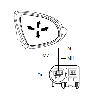
(2) Apply battery voltage and check the operation of the mirror surface.
OK:
|
Battery Connection | Specified Condition |
|---|---|
|
Battery positive (+) → Terminal 3 (MV) Battery negative (-) → Terminal 7 (M+) |
Turns upward |
|
Battery positive (+) → Terminal 7 (M+) Battery negative (-) → Terminal 3 (MV) |
Turns downward |
|
Battery positive (+) → Terminal 6 (MH) Battery negative (-) → Terminal 7 (M+) |
Turns left |
|
Battery positive (+) → Terminal 7 (M+) Battery negative (-) → Terminal 6 (MH) |
Turns right |
If the result is not as specified, replace the outer rear view mirror assembly RH.
(b) Check the operation of the mirror heater. (w/ Mirror Heater)
| (1) Disconnect the outer rear view mirror assembly RH connector. |
|
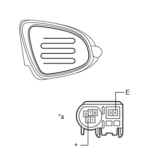
(2) Measure the resistance according to the value(s) in the table below.
Standard Resistance:
|
Tester Connection | Condition |
Specified Condition |
|---|---|---|
|
2 (+) - 4 (E) | 25 |
READ NEXT:
 Reassembly
REASSEMBLY CAUTION / NOTICE / HINT
HINT:
Use the same procedure for the RH side and LH side.
The following procedure is for the LH side.
PROCEDURE 1. INSTALL SIDE TURN SIGNAL LIGHT
Installation
INSTALLATION CAUTION / NOTICE / HINT
HINT:
Use the same procedure for the RH side and LH side.
The following procedure is for the LH side.
PROCEDURE 1. INSTALL OUTER REAR VIEW MIRRO
SEE MORE:
Removal
REMOVAL CAUTION / NOTICE / HINT
The necessary procedures (adjustment, calibration, initialization, or registration) that must be performed after parts are removed and installed, or replaced during No. 1 parking brake cable assembly removal/installation are shown below. Necessary Procedures After P
Rear Axle Hub Bolt(w/ Electric Parking Brake System)
ComponentsCOMPONENTS ILLUSTRATION
*1 NO. 2 PARKING BRAKE WIRE ASSEMBLY
*2 REAR AXLE HUB BOLT
*3 REAR DISC
*4 REAR DISC BRAKE CALIPER ASSEMBLY
*5 REAR FLEXIBLE HOSE
- -
Tightening torque for "Major areas involving basic vehicle pe
