Toyota Camry (XV70): Reassembly
REASSEMBLY
CAUTION / NOTICE / HINT
HINT:
- Use the same procedure for the RH side and LH side.
- The following procedure is for the LH side.
PROCEDURE
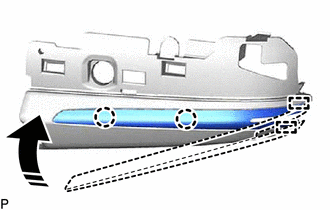
1. INSTALL SIDE TURN SIGNAL LIGHT ASSEMBLY (w/ Side Turn Signal Light)
Click here .gif)
2. INSTALL NO. 2 OUTER MIRROR COVER (for Type A)
(a) Engage the 2 guides and 2 claws to install the No. 2 outer mirror cover as shown in the illustration.
.png) |
Install in this Direction |
3. INSTALL OUTER MIRROR HOLE COVER ASSEMBLY (for Type A)
w/o Panoramic View Monitor System:
Click here
4. INSTALL SIDE TELEVISION CAMERA ASSEMBLY (for Type A)
w/ Panoramic View Monitor System:
Click here
5. INSTALL OUTER MIRROR HOLE COVER WITH SIDE TELEVISION CAMERA ASSEMBLY (for Type A)
w/ Panoramic View Monitor System:
Click here
6. INSTALL OUTER MIRROR COVER (for Type A)
Click here
7. INSTALL OUTER MIRROR (for Type A)
Click here
8. INSTALL VISOR HOUSING (for Type B)
| (a) Engage the 2 guides and 3 claws. |
|
.png)
(b) Using a T25 "TORX" socket wrench, install the visor housing with the 2 screws.
9. INSTALL OUTER MIRROR COVER (for Type B)
Click here
10. INSTALL OUTER MIRROR (for Type B)
Click here
READ NEXT:
 Installation
INSTALLATION CAUTION / NOTICE / HINT
HINT:
Use the same procedure for the RH side and LH side.
The following procedure is for the LH side.
PROCEDURE 1. INSTALL OUTER REAR VIEW MIRRO
Components
COMPONENTS ILLUSTRATION
*A for Type A
*B w/o Panoramic View Monitor System
*C w/ Panoramic View Monitor System
- -
*1 OUTER MIRROR
*2 OU
SEE MORE:
Key-off Operation Function Operates even if Operating Conditions are not Satisfied
DESCRIPTION When the front doors are closed, each power window regulator motor assembly can be operated for approximately 45 seconds after the ignition switch is turned from ON to off by receiving operation permission signals from the main body ECU (multiplex network body ECU). However, when approxi
Removal
REMOVAL CAUTION / NOTICE / HINT
The necessary procedures (adjustment, calibration, initialization or registration) that must be performed after parts are removed and installed, or replaced during air fuel ratio sensor removal/installation are shown below. Necessary Procedures After Parts Removed/I
