Toyota Camry (XV70): Inspection
INSPECTION
PROCEDURE
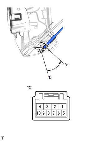
1. INSPECT FRONT DOOR LOCK WITH MOTOR ASSEMBLY LH
| (a) Check the operation of the door lock motor. (1) Apply battery voltage and check the operation of the door lock motor. OK:
If the result is not as specified, replace the front door lock with motor assembly LH. |
|
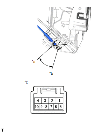
(b) Check the operation of the door unlock detection switch.
(1) Measure the resistance according to the value(s) in the table below.
Standard Resistance:
|
Tester Connection | Condition |
Specified Condition |
|---|---|---|
|
7 - 8 | Locked |
10 k? or higher |
|
7 - 8 | Unlocked |
Below 1 ? |
If the result is not as specified, replace the front door lock with motor assembly LH.
| (c) Check the operation of the door key lock and unlock switch. (1) Measure the resistance according to the value(s) in the table below. Standard Resistance:
If the result is not as specified, replace the front door lock with motor assembly LH. |
|
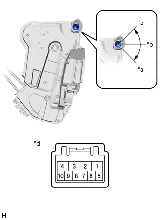
2. INSPECT FRONT DOOR LOCK WITH MOTOR ASSEMBLY RH
| (a) Check the operation of the door lock motor. (1) Apply battery voltage and check the operation of the door lock motor. OK:
If the result is not as specified, replace the front door lock with motor assembly RH. |
|
(b) Check the operation of the door unlock detection switch.
(1) Measure the resistance according to the value(s) in the table below.
Standard Resistance:
|
Tester Connection | Condition |
Specified Condition |
|---|---|---|
|
7 - 8 | Locked |
10 k? or higher |
|
7 - 8 | Unlocked |
Below 1 ? |
If the result is not as specified, replace the front door lock with motor assembly RH.
READ NEXT:
 Installation
INSTALLATION CAUTION / NOTICE / HINT
HINT:
Use the same procedure for the RH side and LH side.
The following procedure is for the LH side.
PROCEDURE 1. PRECAUTION NOTICE: After turning the igni
SEE MORE:
System Diagram
SYSTEM DIAGRAM
Communication Table
Transmitter Receiver
Signal Communication Method
Rear Window Defogger Switch (Air Conditioning Control Assembly)
Air Conditioning Amplifier Assembly
Rear Window Defogger Switch Signal
LIN
Components
COMPONENTS ILLUSTRATION
*1 REAR DISC BRAKE ANTI-SQUEAL SHIM KIT
*2 REAR DISC BRAKE CYLINDER ASSEMBLY
*3 REAR DISC BRAKE PAD
*4 REAR FLEXIBLE HOSE
*5 GASKET
*6 REAR DISC BRAKE PAD WEAR INDICATOR PLATE
*7 REAR NO. 1 DISC BRAKE ANTI-SQUE
