Toyota Camry (XV70): Installation
INSTALLATION
CAUTION / NOTICE / HINT
HINT:
- Use the same procedure for the RH side and LH side.
- The following procedure is for the LH side.
PROCEDURE
1. PRECAUTION
NOTICE:
After turning the ignition switch off, waiting time may be required before disconnecting the cable from the negative (-) battery terminal. Therefore, make sure to read the disconnecting the cable from the negative (-) battery terminal notices before proceeding with work.
Click here .gif)
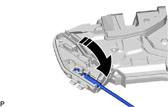
2. INSTALL FRONT DOOR INSIDE LOCKING CABLE ASSEMBLY
(a) Install the front door inside locking cable assembly as shown in the illustration.
.png) |
Install in this Direction |
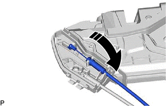
3. INSTALL FRONT DOOR LOCK REMOTE CONTROL CABLE ASSEMBLY
(a) Install the front door lock remote control cable assembly as shown in the illustration.
|
|
Install in this Direction |
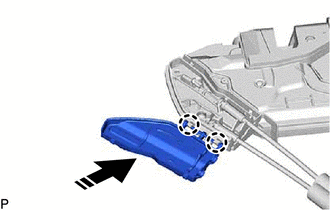
4. INSTALL FRONT DOOR LOCK COVER SUB-ASSEMBLY
(a) Engage the 2 claws as shown in the illustration.
|
|
Install in this Direction |
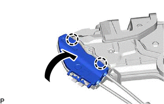
| (b) Engage the 2 claws to install the front door lock cover sub-assembly as shown in the illustration. |
|
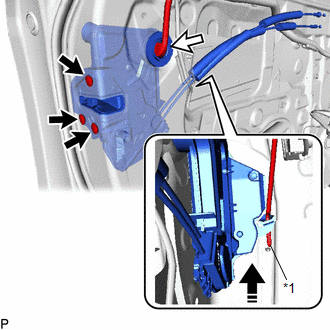
5. INSTALL FRONT DOOR LOCK WITH MOTOR ASSEMBLY
NOTICE:
- When reusing a removed front door lock with motor assembly, replace the door lock wiring harness seal with a new one.
- Do not allow grease or dust to adhere to the door lock wiring harness seal installation surface.
- Reusing a door lock wiring harness seal or using a damaged door lock wiring harness seal may cause water ingress. This may result in a malfunction of the front door lock with motor assembly.
(a) Apply MP grease to the sliding parts of the front door lock with motor assembly.
(b) When reusing the front door lock with motor assembly:
(1) Install a new door lock wiring harness seal to the front door lock with motor assembly.
(c) Connect the front door lock open rod to the front door lock with motor assembly.
|
*1 | Front Door Lock Open Rod |
|
|
Install in this Direction |
HINT:
Make sure that the front door lock open rod is securely connected to the front door lock with motor assembly.
(d) Using a T30 "TORX" socket wrench, install the front door lock with motor assembly with the 3 screws.
Torque:
5.5 N·m {56 kgf·cm, 49 in·lbf}
(e) Connect the connector.
6. INSTALL FRONT DOOR LOCK CYLINDER ASSEMBLY (for Driver Side)
Click here
7. INSTALL FRONT DOOR OUTSIDE HANDLE ASSEMBLY (for Driver Side)
Click here
8. INSTALL FRONT DOOR REAR LOWER FRAME SUB-ASSEMBLY
Click here
9. INSTALL FRONT DOOR GLASS RUN
Click here
10. INSTALL FRONT DOOR PANEL PROTECTOR
Click here
11. INSTALL FRONT DOOR GLASS SUB-ASSEMBLY
Click here
12. INSTALL FRONT DOOR SERVICE HOLE COVER
Click here
13. INSTALL FRONT DOOR INNER GLASS WEATHERSTRIP WITH FRONT DOOR VENT SEAL
Click here
14. INSTALL FRONT DOOR TRIM BOARD SUB-ASSEMBLY
Click here
15. INSTALL FRONT DOOR TRIM PLATE (w/o Courtesy Light)
Click here
16. INSTALL COURTESY LIGHT ASSEMBLY (w/ Courtesy Light)
Click here
17. INSTALL FRONT ARMREST ASSEMBLY
Click here
18. INSTALL MULTIPLEX NETWORK MASTER SWITCH ASSEMBLY WITH FRONT DOOR UPPER ARMREST BASE PANEL (for Driver Side)
Click here
19. INSTALL POWER WINDOW REGULATOR SWITCH ASSEMBLY WITH FRONT DOOR UPPER ARMREST BASE PANEL (for Front Passenger Side)
Click here
20. INSTALL FRONT DOOR ARMREST COVER SUB-ASSEMBLY
Click here
21. INSTALL FRONT DOOR LOWER FRAME BRACKET GARNISH
Click here
22. CONNECT CABLE TO NEGATIVE BATTERY TERMINAL
for A25A-FKS:
Click here
for 2GR-FKS:
Click here
23. INITIALIZE POWER WINDOW CONTROL SYSTEM
Click here
24. INSPECT POWER WINDOW OPERATION
Click here
READ NEXT:
SEE MORE:
 Right Front Wheel ABS Hold Solenoid Control Circuit Short to Battery (C12BB12,...,C12C649)
DESCRIPTION The ABS solenoid relay and solenoid valves are built into the brake actuator assembly.
The front solenoid valve RH controls the brake fluid pressure of the front wheel cylinder RH of the vehicle.
When this DTC is stored, the fail-safe function operates and the ABS solenoid relay is t
Check For Intermittent Problems
CHECK FOR INTERMITTENT PROBLEMS CHECK FOR INTERMITTENT PROBLEMS
HINT: A momentary interruption (open circuit) in the connectors and/or wire harness between the sensors and ECUs can be detected using the Data List function of the Techstream.
(a) Turn the ignition switch off. (b) Connect the Techs
