
Toyota Camry (XV70): Inspection
INSPECTION
PROCEDURE
1. INSPECT MAP LIGHT (ROOF CONSOLE BOX SUB-ASSEMBLY) (for Normal Roof without Door Linked Switch)
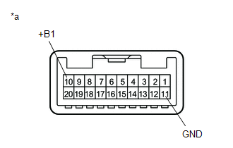
|
*a | Component without harness connected (Map Light (Roof Console Box Sub-assembly)) |
(a) Inspect the map light LH and map light RH.
(1) Apply battery voltage to the connector and check that the map light LH and map light RH come on.
OK:
|
Measurement Condition | Condition |
Specified Condition |
|---|---|---|
|
Battery positive (+) > 10 (+B1) Battery negative (-) > 11 (GND) |
Map light switch LH on |
Map light LH comes on |
|
Map light switch RH on |
Map light RH comes on |
If the result is not as specified, replace the map light (roof console box sub-assembly).
2. INSPECT MAP LIGHT (ROOF CONSOLE BOX SUB-ASSEMBLY) (for Normal Roof with Door Linked Switch)
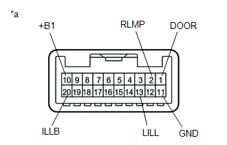
|
*a | Component without harness connected (Map Light (Roof Console Box Sub-assembly)) |
(a) Inspect the map light LH and map light RH.
(1) Apply battery voltage to the connector and check that the map light LH and map light RH come on.
OK:
|
Measurement Condition | Condition |
Specified Condition |
|---|---|---|
|
Battery positive (+) > 10 (+B1) Battery negative (-) > 11 (GND) |
Dome light switch off and map light switch LH on |
Map light LH comes on |
|
Dome light switch off and map light switch RH on |
Map light RH comes on | |
|
Map light switch LH and RH off and dome light switch on |
Map light LH and RH come on | |
|
Battery positive (+) > 10 (+B1) Battery negative (-) > 1 (DOOR) |
Map light switch LH and RH off and door linked switch on |
Map light LH and RH come on |
|
Map light switch LH and RH off and door linked switch off |
Map light LH and RH do not come on | |
|
Battery positive (+) > 10 (+B1) Battery negative (-) > 2 (RLMP) |
Map light switch LH and RH off |
Map light LH and RH come on |
|
Map light switch LH and RH on |
Map light LH and RH do not come on |
If the result is not as specified, replace the map light (roof console box sub-assembly).
(b) Inspect the switch illumination and shift lever illumination.
(1) Apply battery voltage to the connector and check that the switch illumination and shift lever illumination come on.
OK:
|
Measurement Condition | Condition |
Specified Condition |
|---|---|---|
|
Battery positive (+) > 20 (ILLB) Battery negative (-) > 13 (LILL) |
Always | Switch illumination and shift lever illumination come on |
If the result is not as specified, replace the map light (roof console box sub-assembly).
3. INSPECT MAP LIGHT (ROOF CONSOLE BOX SUB-ASSEMBLY) (except Normal Roof)
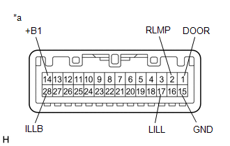
|
*a | Component without harness connected (Map Light (Roof Console Box Sub-assembly)) |
(a) Inspect the map light LH and map light RH.
(1) Apply battery voltage to the connector and check that the map light LH and map light RH come on.
OK:
|
Measurement Condition | Condition |
Specified Condition |
|---|---|---|
|
Battery positive (+) > 14 (+B1) Battery negative (-) > 15 (GND) |
Dome light switch off and map light switch LH on |
Map light LH comes on |
|
Dome light switch off and map light switch RH on |
Map light RH comes on | |
|
Map light switch LH and RH off and dome light switch on |
Map light LH and RH come on | |
|
Battery positive (+) > 14 (+B1) Battery negative (-) > 1 (DOOR) |
Map light switch LH and RH off and door linked switch on |
Map light LH and RH come on |
|
Map light switch LH and RH off and door linked switch off |
Map light LH and RH do not come on | |
|
Battery positive (+) > 14 (+B1) Battery negative (-) > 2 (RLMP) |
Map light switch LH and RH off |
Map light LH and RH come on |
|
Map light switch LH and RH on |
Map light LH and RH do not come on |
If the result is not as specified, replace the map light (roof console box sub-assembly).
(b) Inspect the switch illumination and shift lever illumination.
(1) Apply battery voltage to the connector and check that the switch illumination and shift lever illumination come on.
OK:
|
Measurement Condition | Condition |
Specified Condition |
|---|---|---|
|
Battery positive (+) > 28 (ILLB) Battery negative (-) > 17 (LILL) |
Always | Switch illumination and shift lever illumination come on |
If the result is not as specified, replace the map light (roof console box sub-assembly).
READ NEXT:
SEE MORE:
 Inside Handle Illumination Light Circuit
DESCRIPTION The main body ECU (multiplex network body ECU) controls the operation of the following lights:
Inside Handle Illumination Light LH (No. 1 Interior Illumination Light Assembly LH)
Inside Handle Illumination Light RH (No. 1 Interior Illumination Light Assembly RH)
WIRING DIAGRAM
Fuel Rail Pressure Sensor "A" Circuit Short to Ground (P019011)
DESCRIPTION
The fuel pressure sensor (for high pressure side) is installed on the fuel delivery pipe (for high pressure side). The fuel pressure sensor (for high pressure side) changes the fuel pressure for high pressure side into an electrical signal and sends the signal to the ECM. Then the ECM
