
Toyota Camry (XV70): Installation
INSTALLATION
CAUTION / NOTICE / HINT
HINT:
- Use the same procedure for the RH side and LH side.
- The following procedure is for the LH side.
PROCEDURE
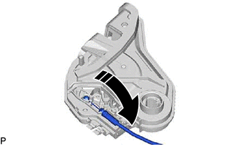
1. INSTALL REAR DOOR INSIDE LOCKING CABLE ASSEMBLY
(a) Install the rear door inside locking cable assembly as shown in the illustration.
.png) |
Install in this Direction |
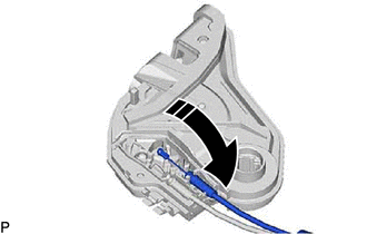
2. INSTALL REAR DOOR LOCK REMOTE CONTROL CABLE ASSEMBLY
(a) Install the rear door lock remote control cable assembly as shown in the illustration.
|
|
Install in this Direction |
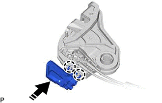
3. INSTALL REAR DOOR LOCK COVER SUB-ASSEMBLY
(a) Engage the 2 claws as shown in the illustration.
|
|
Install in this Direction |
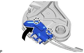
| (b) Engage the 2 claws to install the rear door lock cover sub-assembly as shown in the illustration. |
|
4. INSTALL REAR DOOR LOCK WITH MOTOR ASSEMBLY
NOTICE:
- When reusing a removed rear door lock with motor assembly, replace the door lock wiring harness seal with a new one.
- Do not allow grease or dust to adhere to the door lock wiring harness seal installation surface.
- Reusing a door lock wiring harness seal or using a damaged door lock wiring harness seal may cause water ingress. This may result in a malfunction of the rear door lock with motor assembly.
(a) Apply MP grease to the sliding parts of the rear door lock with motor assembly.
(b) When reusing the rear door lock with motor assembly:
(1) Install a new door lock wiring harness seal to the rear door lock with motor assembly.
(c) Connect the rear door lock with motor assembly to the release plate of the rear door outside handle frame sub-assembly, and set it to the rear door panel.
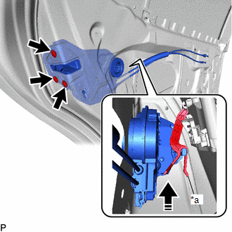
|
*a | Release Plate |
|
|
Install in this Direction |
HINT:
Make sure that the release plate of the rear door outside handle frame sub-assembly is securely connected to the rear door lock with motor assembly.
(d) Using a T30 "TORX" socket wrench, install the rear door lock with motor assembly with the 3 screws.
Torque:
5.5 N·m {56 kgf·cm, 49 in·lbf}
5. INSTALL REAR DOOR GLASS SUB-ASSEMBLY
Click here .gif)
6. INSTALL REAR DOOR QUARTER WINDOW GLASS
Click here
7. INSTALL REAR DOOR REAR LOWER WINDOW FRAME SUB-ASSEMBLY
Click here
8. CONNECT REAR DOOR WEATHERSTRIP
(a) Connect the rear door weatherstrip.
9. INSTALL REAR DOOR GLASS RUN
Click here
10. INSTALL REAR DOOR PANEL PROTECTOR
Click here
11. INSTALL REAR DOOR NO. 1 VENT SEAL
Click here
12. INSTALL REAR DOOR SERVICE HOLE COVER
Click here
13. INSTALL REAR DOOR NO. 2 SERVICE HOLE COVER
Click here
14. INSTALL REAR DOOR INNER GLASS WEATHERSTRIP
Click here
15. INSTALL REAR DOOR TRIM BOARD SUB-ASSEMBLY
Click here
16. INSTALL REAR ARMREST ASSEMBLY
Click here
17. INSTALL REAR POWER WINDOW REGULATOR SWITCH ASSEMBLY WITH REAR DOOR UPPER ARMREST BASE PANEL
Click here
18. INSTALL REAR DOOR ARMREST COVER SUB-ASSEMBLY
Click here
19. CONNECT CABLE TO NEGATIVE BATTERY TERMINAL
for A25A-FKS:
Click here
for 2GR-FKS:
Click here
20. INITIALIZE POWER WINDOW CONTROL SYSTEM
Click here
21. INSPECT POWER WINDOW OPERATION
Click here
READ NEXT:
 Transmitter Battery(w/ Smart Key System)
ReplacementREPLACEMENT PROCEDURE
1. REMOVE TRANSMITTER BATTERY Click here
2. INSTALL TRANSMITTER BATTERY
Click here
Transmitter Battery(w/o Smart Key System)
ReplacementREPLACEMENT PROCEDURE
1. REMOVE TRANSMITTER BATTERY Click here
2. INSTALL TRANSMITTER BATTERY
Click here
Unlock Warning Switch
ComponentsCOMPONENTS ILLUSTRATION
*1 LOWER STEERING COLUMN COVER SUB-ASSEMBLY
*2 UNLOCK WARNING SWITCH ASSEMBLY RemovalREMOVAL PROCEDURE
1. REMOVE LOWER STEERING COLUMN COVER SUB-A
SEE MORE:
Removal
REMOVAL CAUTION / NOTICE / HINT
HINT:
Use the same procedure for the RH side and LH side.
The following procedure is for the LH side.
PROCEDURE 1. REMOVE REAR WHEEL Click here
2. REMOVE REAR AXLE SHAFT NUT
(a) Using SST and a hammer, release the staked part of the rear axle s
Front passenger occupant classification system
Your vehicle is equipped with a front passenger occupant classification
system. This system detects the conditions of the front
passenger seat and activates or deactivates the front passenger
airbag and front passenger knee airbag.
Driver's and front passenger's seat belt reminder light
S
