
Toyota Camry (XV70): Unlock Warning Switch
Components
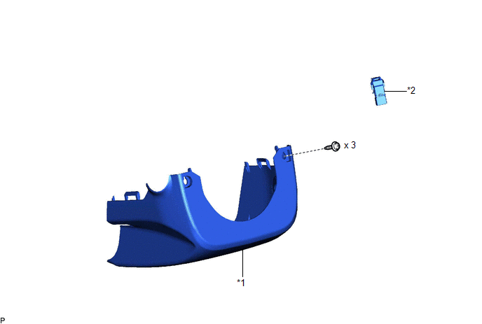
COMPONENTS
ILLUSTRATION
|
*1 | LOWER STEERING COLUMN COVER SUB-ASSEMBLY |
*2 | UNLOCK WARNING SWITCH ASSEMBLY |
Removal
REMOVAL
PROCEDURE
1. REMOVE LOWER STEERING COLUMN COVER SUB-ASSEMBLY
Click here
.gif)
2. REMOVE UNLOCK WARNING SWITCH ASSEMBLY
(a) Insert the key into the ignition key cylinder.
| (b) Disconnect the connector. |
|
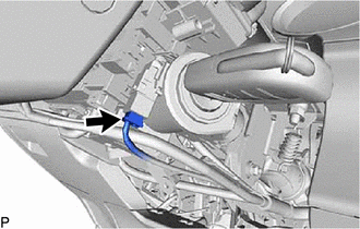
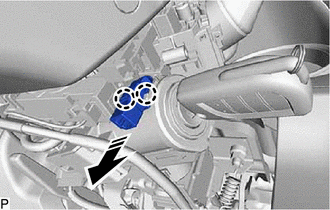
(c) Disengage the 2 claws and remove the unlock warning switch assembly as shown in the illustration.
.png) |
Remove in this Direction |
Inspection
INSPECTION
PROCEDURE
1. INSPECT UNLOCK WARNING SWITCH ASSEMBLY
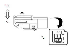
|
*a | Component without harness connected (Unlock Warning Switch Assembly) |
|
*b | Switch not pushed |
|
*c | Switch pushed |
(a) Measure the resistance according to the value(s) in the table below.
Standard Resistance:
|
Tester Connection | Condition |
Specified Condition |
|---|---|---|
|
1 - 2 | Switch not pushed (Key removed) |
10 k? or higher |
|
1 - 2 | Switch pushed (Key inserted) |
Below 1 ? |
If the result is not as specified, replace the unlock warning switch assembly.
Installation
INSTALLATION
PROCEDURE
1. INSTALL UNLOCK WARNING SWITCH ASSEMBLY
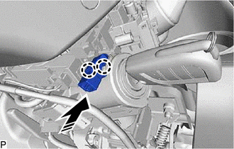
(a) Engage the 2 claws to install the unlock warning switch assembly as shown in the illustration.
.png) |
Install in this Direction |
(b) Connect the connector.
(c) Remove the key from the ignition key cylinder.
2. INSTALL LOWER STEERING COLUMN COVER SUB-ASSEMBLY
Click here .gif)
READ NEXT:
 Wireless Door Lock Buzzer
ComponentsCOMPONENTS ILLUSTRATION
*1 FRONT FENDER LINER LH
*2 FRONT WHEEL OPENING EXTENSION PAD LH
*3 WIRELESS DOOR LOCK BUZZER
- - RemovalREMOVAL PROCEDURE
1. REMO
Precaution
PRECAUTION PRECAUTION FOR DISCONNECTING CABLE FROM NEGATIVE BATTERY TERMINAL
NOTICE: When disconnecting the cable from the negative (-) battery terminal, initialize the following systems after the ca
SEE MORE:
Door Control Transmitter(w/o Smart Key System)
ComponentsCOMPONENTS ILLUSTRATION
*1 TRANSMITTER BATTERY
*2 TRANSMITTER BATTERY HOUSING COVER
*3 TRANSMITTER HOUSING COVER
*4 TRANSMITTER HOUSING CASE RemovalREMOVAL PROCEDURE
1. REMOVE TRANSMITTER BATTERY Click here
InspectionINSPECTION PROCEDURE
1. INSPECT D
System Diagram
SYSTEM DIAGRAM
Transmitting ECU (Transmitter)
Receiving ECU Signal
Communication Method
Skid control ECU (brake actuator assembly)
Steering angle sensor Steering angle sensor request signal
CAN communication line
Steering angle sensor
