
Toyota Camry (XV70): Door Control Transmitter(w/o Smart Key System)
Components
COMPONENTS
ILLUSTRATION
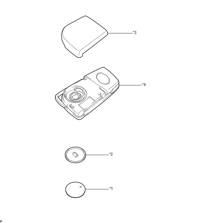
|
*1 | TRANSMITTER BATTERY |
*2 | TRANSMITTER BATTERY HOUSING COVER |
|
*3 | TRANSMITTER HOUSING COVER |
*4 | TRANSMITTER HOUSING CASE |
Removal
REMOVAL
PROCEDURE
1. REMOVE TRANSMITTER BATTERY
Click here

Inspection
INSPECTION
PROCEDURE
1. INSPECT DOOR CONTROL TRANSMITTER MODULE SET SUB-ASSEMBLY
(a) Inspect the operation of the door control transmitter module set sub-assembly.
(1) Remove the transmitter battery from the door control transmitter module set sub-assembly.
Click here 
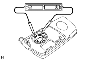
| (2) Install a new or known good transmitter battery. Click here
NOTICE: When replacing the transmitter battery, before starting work, remove static electricity that has built up in the body by touching, for example, the vehicle to prevent the door control transmitter module set sub-assembly from being damaged. HINT: If a new or known good transmitter battery is not available, first connect 2 new 1.5 V batteries in series. Then connect leads to the batteries and apply 3 V to the door control transmitter module set sub-assembly, as shown in the illustration. |
|
(3) From outside the vehicle, approximately 1 m (3.28 ft.) from the driver door outside door handle, test the door control transmitter module set sub-assembly by pointing its key plate at the vehicle and pressing an door control transmitter module set sub-assembly switch.
OK:
The door lock can be operated via the door control transmitter module set sub-assembly.
- The operational area differs depending on the user, the way the door control transmitter module set sub-assembly is held, and the location.
- The weak radio waves of the door control transmitter module set sub-assembly may be affected if the area has strong radio waves or noise. The door control transmitter module set sub-assembly operation area may be shortened or the door control transmitter module set sub-assembly may not function.
(b) Inspect the transmitter battery capacity.
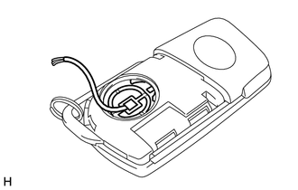
(1) Remove the transmitter battery from the door control transmitter module set sub-assembly that does not operate. Attach a lead wire (0.6 mm (0.0236 in.) in diameter or less including wire sheath) with tape or equivalent to the negative terminal.
Click here
NOTICE:
Do not wrap the lead wire around a terminal, wedge it between the terminals, or solder it. A terminal may be deformed or damaged, and the transmitter battery will not be able to be installed correctly.
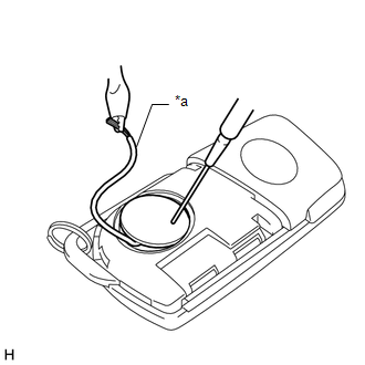
| (2) Carefully pull the lead wire out from the position shown in the illustration and install the previously removed transmitter battery. NOTICE: When replacing the transmitter battery, before starting work, remove static electricity that has built up in the body by touching, for example, the vehicle to prevent the door control transmitter module set sub-assembly from being damaged. |
|
| (3) Check the transmitter battery voltage. HINT: Measure the transmitter battery voltage while pressing the lock or unlock switch on the door control transmitter module set sub-assembly. Standard Voltage:
If the result is not as specified, replace the transmitter battery. |
|
Installation
INSTALLATION
PROCEDURE
1. INSTALL TRANSMITTER BATTERY
Click here

READ NEXT:
 Components
COMPONENTS ILLUSTRATION
*A for Front Passenger Side
*B for Driver Side
*C w/o Courtesy Light
*D w/ Courtesy Light
*1 COURTESY LIGHT ASSEMBLY
*2 FRONT AR
Removal
REMOVAL CAUTION / NOTICE / HINT
The necessary procedures (adjustment, calibration, initialization, or registration) that must be performed after parts are removed and installed, or replaced during fr
SEE MORE:
Position Initialization Incomplete (B2343)
DESCRIPTION This DTC is stored when the sliding roof ECU (sliding roof drive gear assembly) or roof sunshade ECU (sliding roof drive gear assembly) has not been initialized. Sliding Roof
DTC No. Detection Item
DTC Detection Condition
Trouble Area
B2343 Position Initia
Relay
InspectionINSPECTION PROCEDURE
1. INSPECT ST RELAY (a) Check the resistance.
(1) Measure the resistance according to the value(s) in the table below.
Standard Resistance:
Tester Connection Condition
Specified Condition
3 - 5 Battery voltage not applied to termin
