
Toyota Camry (XV70): Relay
Inspection
INSPECTION
PROCEDURE
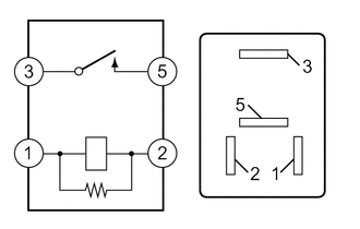
1. INSPECT ST RELAY
| (a) Check the resistance. (1) Measure the resistance according to the value(s) in the table below. Standard Resistance:
If the result is not as specified, replace the ST relay. |
|
Inspection
INSPECTION
PROCEDURE
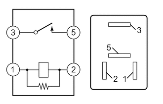
1. INSPECT ST RELAY
| (a) Check the resistance. (1) Measure the resistance according to the value(s) in the table below. Standard Resistance:
If the result is not as specified, replace the ST relay. |
|
READ NEXT:
 Components
COMPONENTS ILLUSTRATION
*1 AIR CLEANER ASSEMBLY WITH AIR CLEANER HOSE
*2 INLET AIR CLEANER ASSEMBLY
*3 BATTERY CLAMP SUB-ASSEMBLY
*4 COOL AIR INTAKE DUCT SEAL
Removal
REMOVAL CAUTION / NOTICE / HINT
The necessary procedures (adjustment, calibration, initialization or registration) that must be performed after parts are removed and installed, or replaced starter a
SEE MORE:
Components
COMPONENTS ILLUSTRATION
*1 VVT SENSOR (for Intake Side of Bank 1)
*2 VVT SENSOR (for Exhaust Side of Bank 1)
*3 VVT SENSOR (for Intake Side of Bank 2)
*4 VVT SENSOR (for Exhaust Side of Bank 2)
N*m (kgf*cm, ft.*lbf): Specified torque
Mute Signal Circuit between Stereo Component Amplifier and Telematics Transceiver
DESCRIPTION The DCM (telematics transceiver) sends a mute signal to the stereo component amplifier assembly.
The stereo component amplifier assembly controls the volume according to the mute signal from the DCM (telematics transceiver). WIRING DIAGRAM
CAUTION / NOTICE / HINT
NOTICE:
Depen
