Toyota Camry (XV70): Components
COMPONENTS
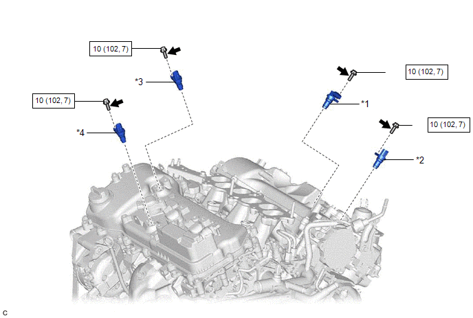
ILLUSTRATION
|
*1 | VVT SENSOR (for Intake Side of Bank 1) |
*2 | VVT SENSOR (for Exhaust Side of Bank 1) |
|
*3 | VVT SENSOR (for Intake Side of Bank 2) |
*4 | VVT SENSOR (for Exhaust Side of Bank 2) |
.png) |
N*m (kgf*cm, ft.*lbf): Specified torque |
.png) |
Adhesive 1324 |
|
★ | Precoated part |
- | - |
READ NEXT:
 Removal
REMOVAL CAUTION / NOTICE / HINT
The necessary procedures (adjustment, calibration, initialization or registration) that must be performed after parts are removed and installed, or replaced during VV
Installation
INSTALLATION PROCEDURE 1. INSTALL VVT SENSOR (for Exhaust Side of Bank 2)
(a) Apply a light coat of engine oil to the O-ring of the VVT sensor. NOTICE:
If reusing the VVT sensor, be sure to inspec
Crankshaft Position Sensor
ComponentsCOMPONENTS ILLUSTRATION
*1 CRANKSHAFT POSITION SENSOR
*2 CRANKSHAFT POSITION SENSOR PROTECTOR
N*m (kgf*cm, ft.*lbf): Specified torque
- - Remova
SEE MORE:
Parts Location
PARTS LOCATION ILLUSTRATION
*1 ECM
*2 ENGINE ROOM RELAY BLOCK AND JUNCTION BLOCK ASSEMBLY
- ST RELAY - EFI-MAIN NO. 1 FUSE - J/B-B FUSE - ETCS FUSE ILLUSTRATION
*A w/ Shift Paddle Switch
- -
*1 SHIFT LOCK CONTROL UNIT ASSEMBLY
- TRANSMISSIO
Left Front Wheel Speed Sensor Circuit Short to Ground or Open (C050014)
DESCRIPTION Refer to DTC C050012 Click here
DTC No. Detection Item
DTC Detection Condition Trouble Area
C050014 Left Front Wheel Speed Sensor Circuit Short to Ground or Open
A short or open circuit is detected in the speed sensor signal circuit for 0.12 seconds or
© 2023-2026 Copyright www.tocamry.com
