Toyota Camry (XV70): Crankshaft Position Sensor
Components
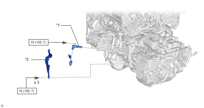
COMPONENTS
ILLUSTRATION
|
*1 | CRANKSHAFT POSITION SENSOR |
*2 | CRANKSHAFT POSITION SENSOR PROTECTOR |
.png) |
N*m (kgf*cm, ft.*lbf): Specified torque |
- | - |
Removal
REMOVAL
CAUTION / NOTICE / HINT
The necessary procedures (adjustment, calibration, initialization or registration) that must be performed after parts are removed and installed, or replaced during crankshaft position sensor removal/installation are shown below.
Necessary Procedures After Parts Removed/Installed/Replaced|
Replaced Part or Performed Procedure |
Necessary Procedure | Effect/Inoperative Function when Necessary Procedure not Performed |
Link |
|---|---|---|---|
| Gas leak from exhaust system is repaired |
Inspection after repair |
|
|
PROCEDURE
1. REMOVE EXHAUST MANIFOLD SUB-ASSEMBLY LH (TWC: Front Catalyst)
Click here
.gif)
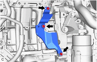
2. REMOVE CRANKSHAFT POSITION SENSOR PROTECTOR
| (a) Remove the 3 bolts and crankshaft position sensor protector from the cylinder block sub-assembly and oil pan sub-assembly. |
|
3. REMOVE CRANKSHAFT POSITION SENSOR
| (a) Disconnect the crankshaft position sensor connector. |
|
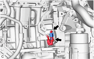
(b) Remove the bolt and crankshaft position sensor from the cylinder block sub-assembly.
NOTICE:
If the crankshaft position sensor has been struck or dropped, replace it.
Installation
INSTALLATION
PROCEDURE
1. INSTALL CRANKSHAFT POSITION SENSOR
(a) Apply a light coat of engine oil to the O-ring of the crankshaft position sensor.
NOTICE:
If reusing the crankshaft position sensor, be sure to inspect the O-ring.
(b) Install the crankshaft position sensor to the cylinder block sub-assembly with the bolt.
Torque:
10 N·m {102 kgf·cm, 7 ft·lbf}
NOTICE:
- If the crankshaft position sensor has been struck or dropped, replace it.
- Make sure that the O-ring is not cracked or moved out of place when installing the crankshaft position sensor.
(c) Connect the crankshaft position sensor connector.
2. INSTALL CRANKSHAFT POSITION SENSOR PROTECTOR
(a) Install the crankshaft position sensor protector to the cylinder block sub-assembly and oil pan sub-assembly with the 3 bolts.
Torque:
10 N·m {102 kgf·cm, 7 ft·lbf}
3. INSTALL EXHAUST MANIFOLD SUB-ASSEMBLY LH (TWC: Front Catalyst)
Click here .gif)
READ NEXT:
 Components
COMPONENTS ILLUSTRATION
*1 AIR CLEANER ASSEMBLY WITH AIR CLEANER HOSE
*2 COOL AIR INTAKE DUCT SEAL
*3 ECM
*4 INLET AIR CLEANER ASSEMBLY
*5 NO. 1 ECM BRA
Removal
REMOVAL CAUTION / NOTICE / HINT
The necessary procedures (adjustment, calibration, initialization or registration) that must be performed after parts are removed and installed, or replaced during EC
SEE MORE:
Installation
INSTALLATION PROCEDURE 1. INSTALL FUEL LID OPENER SWITCH
(a) Engage the 2 claws to install the fuel lid opener switch as shown in the illustration.
Install in this Direction 2. INSTALL NO. 1 INSTRUMENT PANEL SUB-ASSEMBLY
Click here
3. CONNECT HOOD LOCK CONTROL
Transmitter ID not Received (Main) (C2126)
DESCRIPTION If ID registration via the automatic ID registration function is canceled or the tire pressure warning ECU and receiver does not receive data from the tire pressure warning valve and transmitters after the tire pressure warning valve and transmitter ID registration is completed using the
