Toyota Camry (XV70): Removal
REMOVAL
CAUTION / NOTICE / HINT
The necessary procedures (adjustment, calibration, initialization or registration) that must be performed after parts are removed and installed, or replaced during brake pedal support assembly removal/installation are shown below.
Necessary Procedures After Parts Removed/Installed/Replaced|
Replaced Part or Performed Procedure |
Necessary Procedure | Effect/Inoperative Function when Necessary Procedure not Performed |
Link |
|---|---|---|---|
|
Disconnect cable from negative battery terminal |
Perform steering sensor zero point calibration |
Lane tracing assist system |
|
|
Pre-collision system | |||
|
Memorize steering angle neutral point |
Parking assist monitor system |
| |
|
Panoramic view monitor system |
|
PROCEDURE
1. PRECAUTION
NOTICE:
After turning the ignition switch off, waiting time may be required before disconnecting the cable from the negative (-) battery terminal. Therefore, make sure to read the disconnecting the cable from the negative (-) battery terminal notices before proceeding with work.
Click here .gif)
2. REMOVE BATTERY
for A25A-FKS: Click here
for 2GR-FKS: Click here
3. DRAIN BRAKE FLUID
NOTICE:
If brake fluid leaks onto any painted surface, immediately wash it off.
4. DISCONNECT BRAKE LINE
|
(a) Using a union nut wrench, disconnect the 2 brake lines from the brake master cylinder sub-assembly. NOTICE:
|
|
.png)
5. REMOVE NO. 1 INSTRUMENT PANEL UNDER COVER SUB-ASSEMBLY
Click here
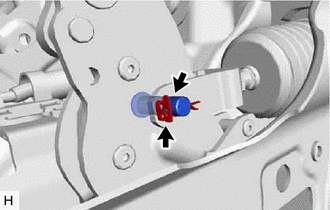
6. REMOVE STOP LIGHT SWITCH ASSEMBLY
Click here
7. REMOVE PUSH ROD PIN
| (a) Remove the clip and push rod pin. |
|
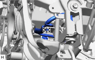
8. REMOVE BRAKE PEDAL SUPPORT ASSEMBLY
| (a) Disengage the clamp to separate the wire harness from the brake pedal support assembly. |
|
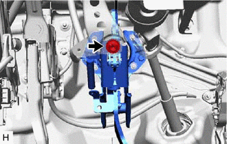
| (b) Remove the bolt and separate the brake pedal support assembly from the instrument panel reinforcement assembly. |
|
(c) Remove the 2 clips.
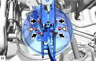
.png) |
Nut |
.png) |
Clip |
HINT:
Depending on the vehicle, the clips may not be installed.
(d) Remove the 4 nuts and push the brake booster assembly toward the engine compartment.
NOTICE:
- Do not apply excessive force to the brake lines.
- Do not apply excessive force to the wire harness.
(e) Remove the brake pedal support assembly while avoiding the stud bolts of the brake booster assembly and brake booster support base.
NOTICE:
Be careful not to deform the bracket of the instrument panel reinforcement assembly.
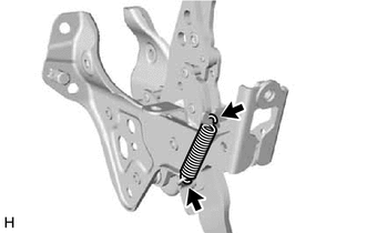
9. REMOVE BRAKE PEDAL RETURN SPRING
| (a) Remove the brake pedal return spring from the brake pedal support assembly. |
|
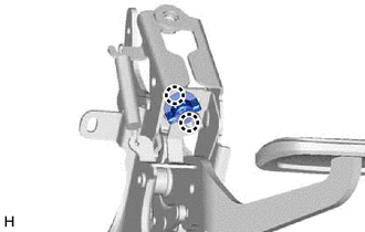
10. REMOVE STOP LIGHT SWITCH MOUNTING ADJUSTER
| (a) Disengage the 2 claws and remove the stop light switch mounting adjuster. |
|
11. REMOVE BRAKE PEDAL PAD
(a) Remove the brake pedal pad from the brake pedal support assembly.
READ NEXT:
 Adjustment
ADJUSTMENT PROCEDURE 1. INSPECT AND ADJUST BRAKE PEDAL HEIGHT
(a) Remove the front door scuff plate LH. Click here
(b) Remove the cowl side trim sub-assembly LH.
Click here (c) Remove the No
Installation
INSTALLATION PROCEDURE 1. INSTALL BRAKE PEDAL PAD
(a) Install the brake pedal pad to the brake pedal support assembly. 2. INSTALL STOP LIGHT SWITCH MOUNTING ADJUSTER
(a) Engage the 2 claws to inst
SEE MORE:
Installation
INSTALLATION PROCEDURE 1. INSTALL DCM (TELEMATICS TRANSCEIVER)
2. INSTALL NAVIGATION ECU (w/ Navigation System) 3. INSTALL NO. 1 TELEPHONE BRACKET
(a) w/o Navigation System: (1) Install the No. 1 telephone bracket with the screw.
(b) w/ Navigation System: (1) Install the No. 1 telephone bracke
Inspection
INSPECTION PROCEDURE 1. INSPECT FLOW SHUTTING VALVE (WATER BY-PASS HOSE ASSEMBLY)
(a) Measure the resistance according to the value(s) in the table below.
Standard Resistance:
Tester Connection Condition
Specified Condition
1 - 2 20°C (68°F)
22 to 28 ]
