Toyota Camry (XV70): Installation
INSTALLATION
PROCEDURE
1. INSTALL FRONT NO. 1 STABILIZER BAR BUSHING (for LH Side)
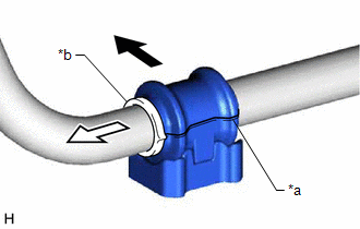
(a) Install the front No. 1 stabilizer bar bushing to the front stabilizer bar as shown in the illustration.
|
*a | Cutout |
|
*b | Stopper Ring |
.png) |
Front of the Vehicle |
.png) |
Outside of the Vehicle |
NOTICE:
- Install the front No. 1 stabilizer bar bushing so that the cutout is facing the rear of the vehicle.
- Install the front No. 1 stabilizer bar bushing onto the front stabilizer bar so that the stopper ring of the front stabilizer bar faces the outside of the vehicle.
2. INSTALL FRONT NO. 1 STABILIZER BAR BUSHING (for RH Side)
HINT:
Perform the same procedure as for the LH side.
3. INSTALL FRONT STABILIZER BAR
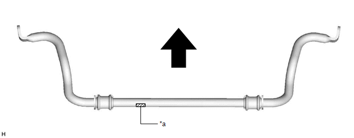
(a) Install the front stabilizer bar with the 2 front stabilizer bar bushings to the front frame assembly.
NOTICE:
Make sure that the identification mark is positioned as shown in the illustration.
|
*a | Identification Mark |
- | - |
|
|
Front of the Vehicle |
- | - |
4. INSTALL FRONT NO. 1 STABILIZER BRACKET LH
(a) Install the front No. 1 stabilizer bracket LH to the front frame assembly with the 2 bolts.
Torque:
44 N
READ NEXT:
 Components
COMPONENTS ILLUSTRATION
*A for A25A-FKS
*B for AWD
*1 FRONT FRAME ASSEMBLY
*2 FUEL DELIVERY GUARD
*3 STEERING GEAR HEAT INSULATOR
*4 WIRE HARNES
Removal
REMOVAL CAUTION / NOTICE / HINT
The necessary procedures (adjustment, calibration, initialization, or registration) that must be performed after parts are removed and installed, or replaced during f
SEE MORE:
Speaker Circuit
DESCRIPTION for 6 Speakers
If there is a short in a speaker circuit, the radio and display receiver assembly detects it and stops output to the speakers.
Thus sound cannot be heard from the speakers even if there is no malfunction in the radio and display receiver assembly, DCM (telematics tr
How To Proceed With Troubleshooting
CAUTION / NOTICE / HINT HINT: *: Use the Techstream. PROCEDURE
1.
VEHICLE BROUGHT TO WORKSHOP
NEXT
2.
CUSTOMER PROBLEM ANALYSIS
HINT:
In troubleshooting, confirm that the problem symptoms have been accurately identified. Preconceptions
